Introduction
Hi. Thank you for showing Interest in this project. This Project was my engineering’s final year capstone project. It took me a month to make this Project and I had fun building it. Below I am writing a step by step DIY guide to help you build your own CNC Drawing Robot. The guide is quite long with both text and video. I have given most details so that you will not feel any problem if you are new to making projects of this kind.
The Crazy Engineer’s Drawing Robot or Arduino GRBL CoreXY Servo Drawbot is a CNC based drawing robot. It is open source and
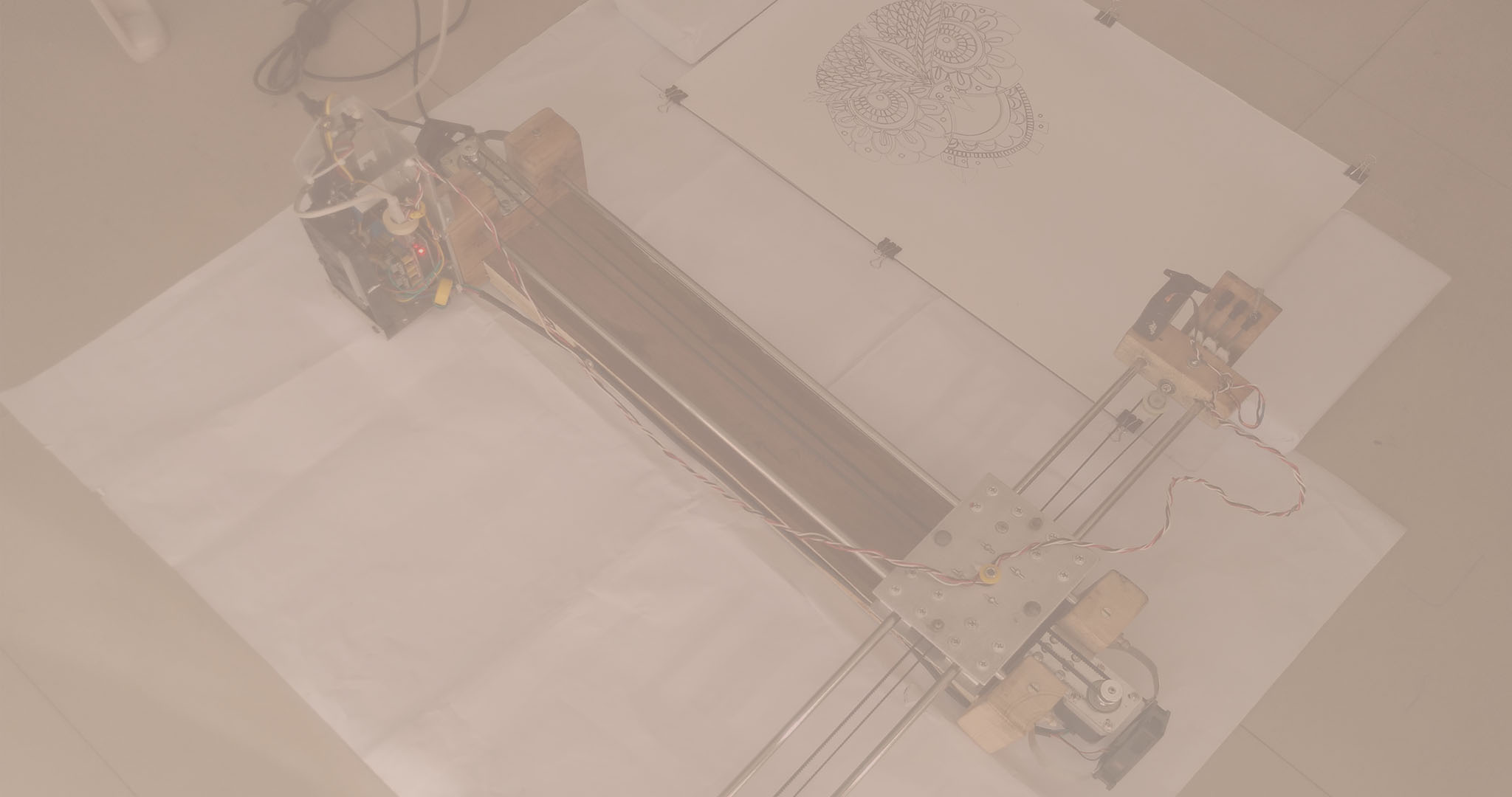
Crazy Engineer’s Drawing Robot is a simple CNC Drawing Robot, capable of writing or drawing on almost any flat surface. It can write with gel pens, permanent markers, and a variety of other writing implements to handle an endless number of applications. Its writing head extends beyond the machine, making it possible to draw on objects bigger than the machine itself.
Suggested applications include:
• Decoration Drawing
• Computer artwork
• Technical drawing
• Notes and cards
• Writing signatures
• Signing diplomas and other certificates
• "Hand-written" lists
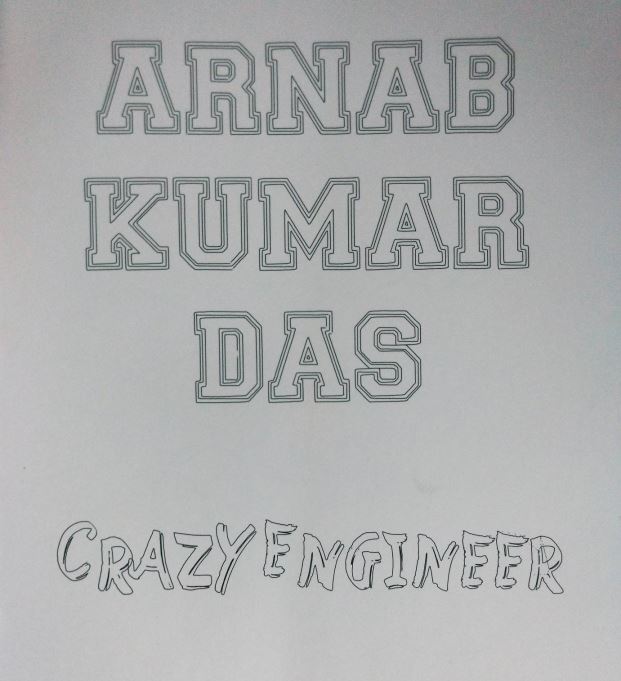 Vector Text
 Raster Drawing
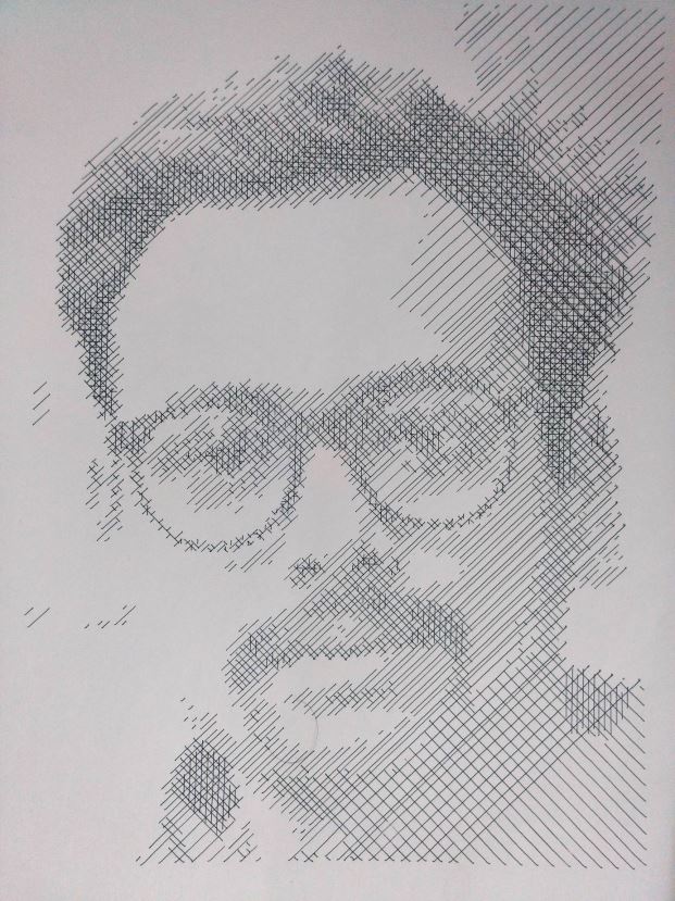 Vector Drawing
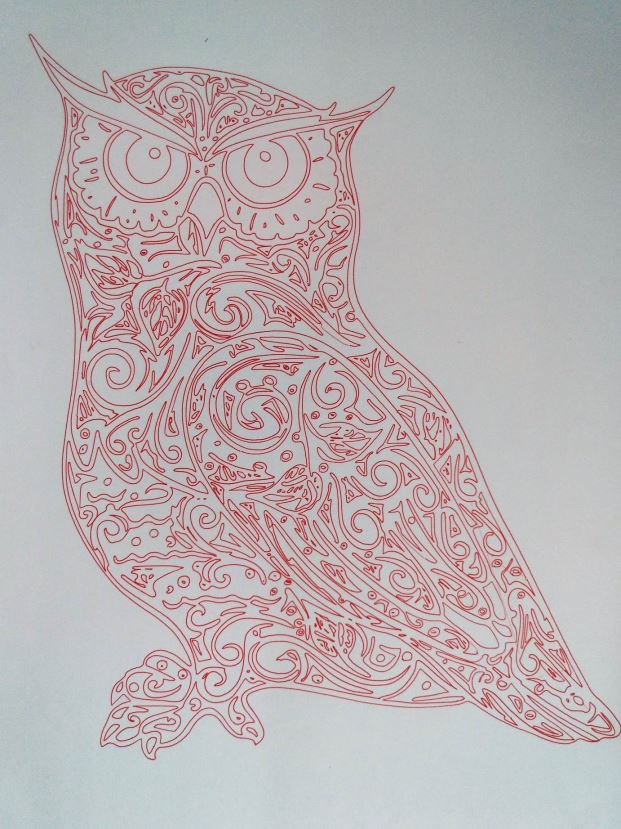 Vector Drawing
Project Motivation
When I was in
If you Google DRAWBOT you will come across
• AxiDraw is very fascinating and quite a beautiful product.
• TRS Drawbot
• The Polar Plotter
• Pen Plotter
• Makelangelo is the hanging one.
• Cartesio
• 4xiDraw is CoreXY based.
Collectively I studied all of these and found it cool. But they were mostly using A4 paper so I made one for myself with the largest work area of all above. My Crazy Drawing Robot can handle paper as big as ARCH B.
The dreams of yesterday are the hopes of today and the reality of tomorrow. Science has not yet mastered prophecy. We predict too much for the next year and yet far too little for the next ten.
Project Comparison with AxiDraw
Crazy Engineer’s Drawbot is similar as well as different from AxiDraw:
• Crazy Engineer’s Drawbot is a Cartesian CoreXY movement (H-bot I think) similar to AxiDraw.
• Crazy Engineer’s Drawbot is based on Arduino, while AxiDraw is based on the EBB Driver board
• Crazy Engineer’s Drawbot has a large working area (45×38), like an ARCH B paper bigger than A3, while AxiDraw has a normal working area (30×20), like an A4 paper.
• Crazy Engineer’s Drawbot is Made of Wood to reduce cost, while AxiDraw is in metal (? this is not very clear watching the pictures)
• AxiDraw can write with a fountain pen, Crazy Engineer’s Drawbot not (yet)
• AxiDraw costs 475$, Crazy Engineer’s Drawbot costs 150$. Not bad!
 CNC After Drawing
Project Bill of Material
• 2 x NEMA 17 Steppers 1.8 Degree Step 12v Torque more than 5kg/cm
• 4 x 8mm smooth rods (I used 8mm, will Suggest you
• 8 x SC8UU (Will suggest u
• 2 x 20-Tooth GT2 pulleys
• 10 x F623ZZ Bearings (I used Plastic Pulleys to reduce cost)
• 1 x Micro Servo SG90 (Later I Used a Bigger Servo for Quality)
• 1 x Arduino UNO
• 1 x CNC Shield V3
• 2 x Pololu Step Sticks A4988 Stepper Driver
• 1 x GT2 Belt (3 meters long)
• 1 x Hard Wood 1mx20cmx4cm
• 8 x 30mm M3 screws with nuts
• 3 x BLDC Fan (Not Necessary if you are not in
• 1 x Aluminium Sheet 3mm
• 20 x 1 Inch Screw m4
• 20 x 3 Inch Screw M4
• 1 x Inch Screw m3
• 1 x Wire 5m
• 1 x SMPS 12v 5A
• 20 x Washers M4
• 6 x 4 Inch Screw M3
• 1 x Soldering Wire
• 1 x Solder
• 1 x Jig Saw
• 1 x Jig Saw Blade for wood cutting
• 1 x USB Wire
• 4 x Special Liquid ink PEN of multiple
• 5x Ferrite Core
• Miscellaneous Tools and Components
Core[X,Y]
Core[X
Design Advantage: The Design of the Drawing Robot is Compact as the
Fast: CoreXY
Simple: CoreXY can be implemented with only three structural plates, all of which can nest during fabrication.
Flexible: Whether your medium is fabric or aluminium, the principle behind CoreXY permits motion stages to be rendered in a variety of materials and a wide range of sizes.
 CoreXY Working
Building The CNC's Body
Build Process
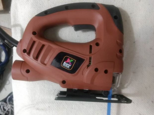 JK Super Drive Jig Saw Used for All Cutting
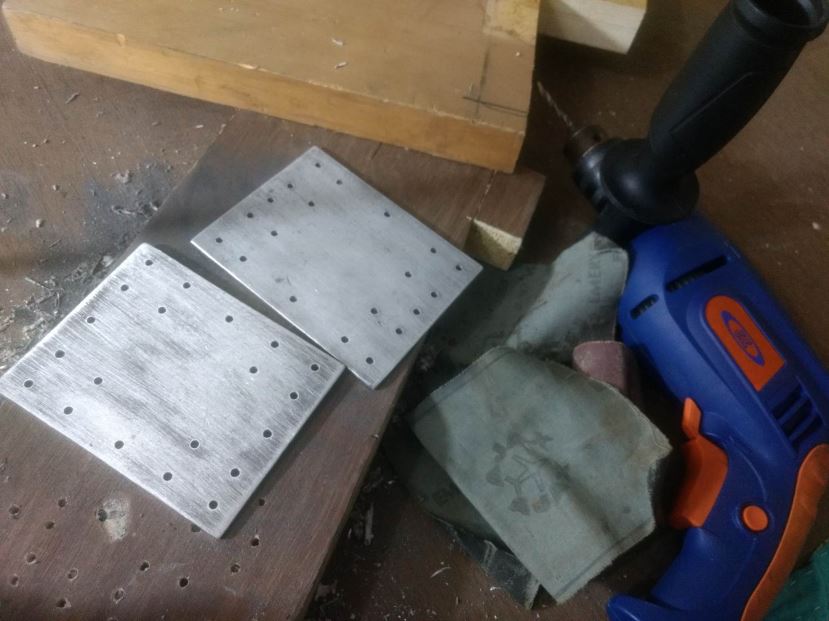 JK 13mm Drill with Al Plates
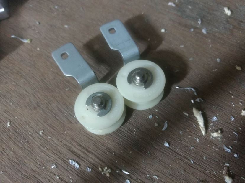 Plastic Pulleys
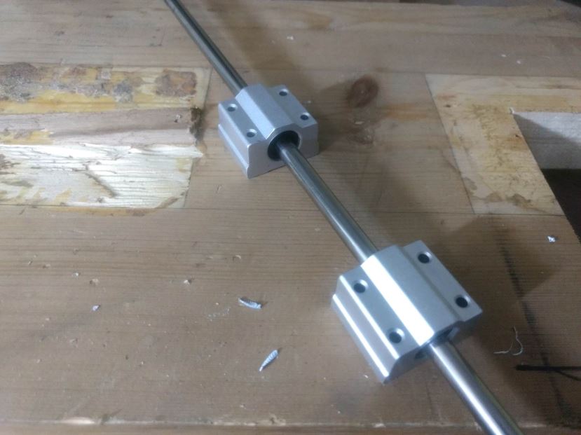 Linear Bearings with Shaft
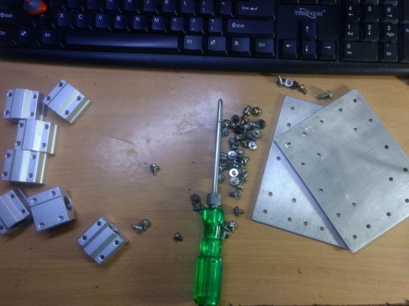 Assembling the bearings
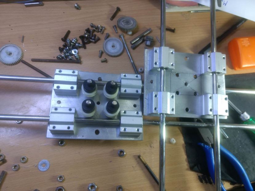 Pulleys in Central Carriage Assembly
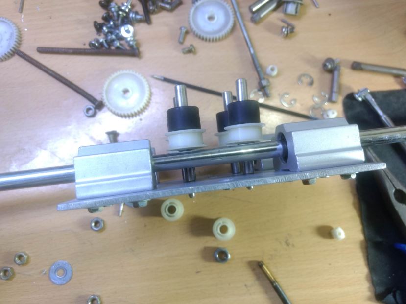 Pulleys in Central Carriage Assembly
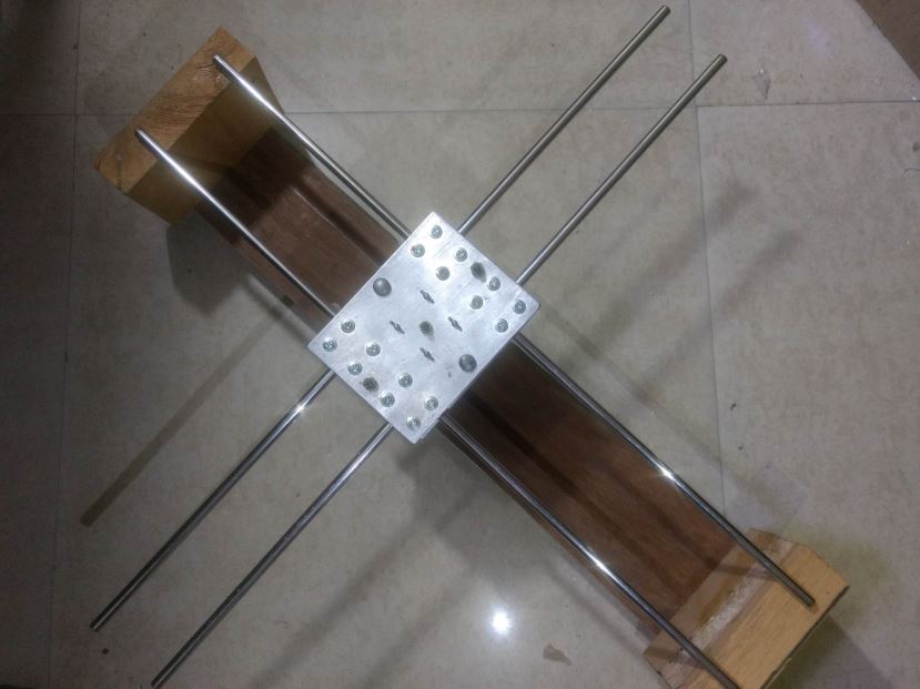 X and Y Axis Before Mounting on Chassis
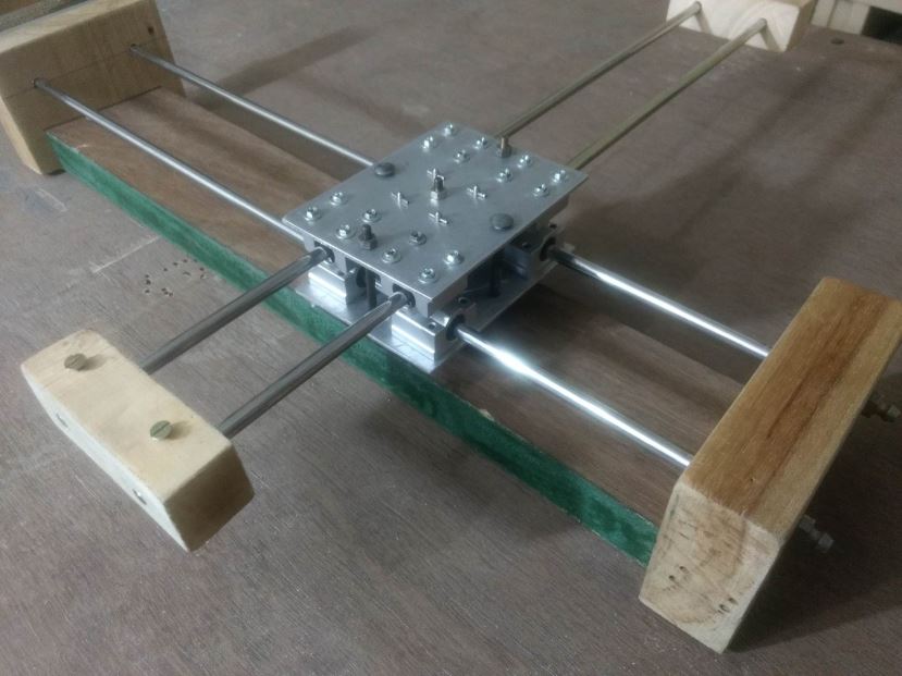 X and Y Axis After Mounting on Chassis
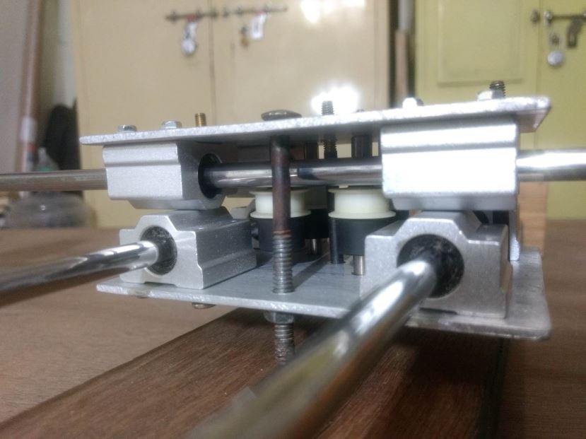 X and Y Axis After Mounting on Chassis
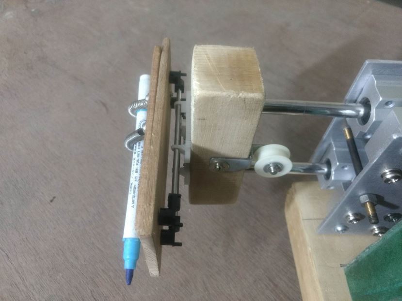 Pen Holder Bottom View
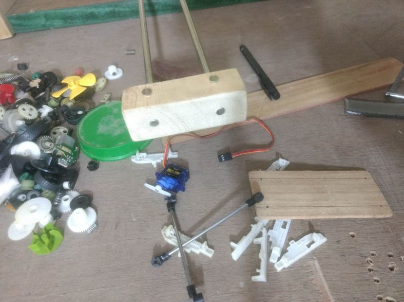 Pen Holder Components
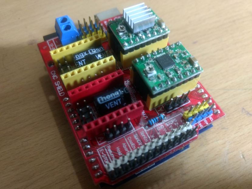 Arduino With CNC Shield
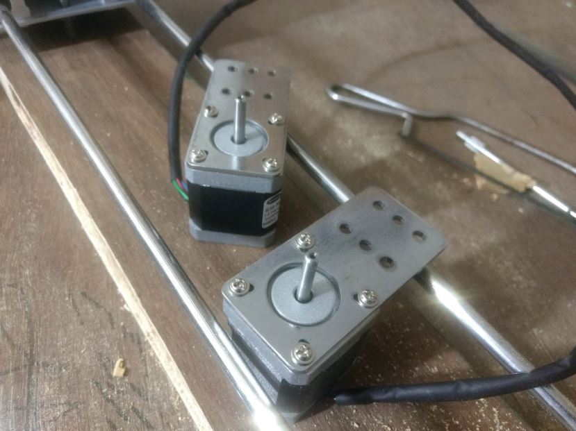 5.5Kgcm Stepper with Clamps
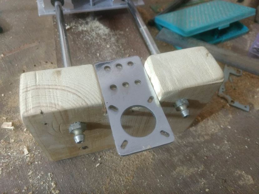 Stepper being Mounted on Chassis
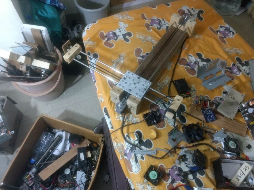 Mess During the Project Making
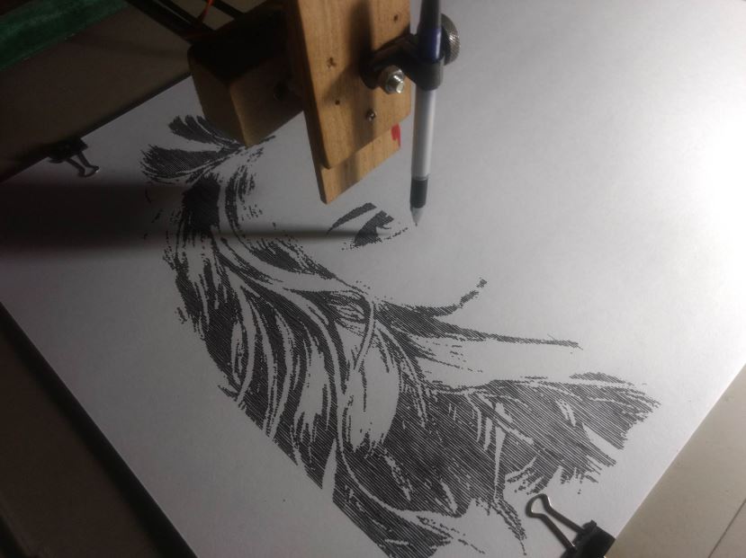 Raster Drawing Drawing Crazy Engineer’s Drawbot
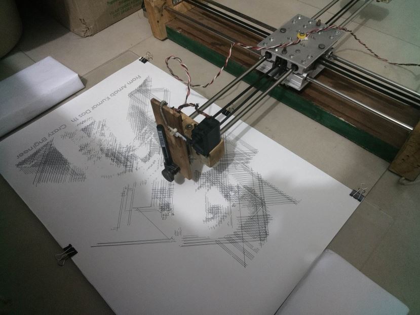 Vector Drawing Crazy Engineer’s Drawbot
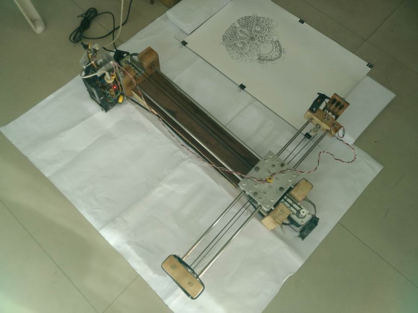 After Drawing Completion
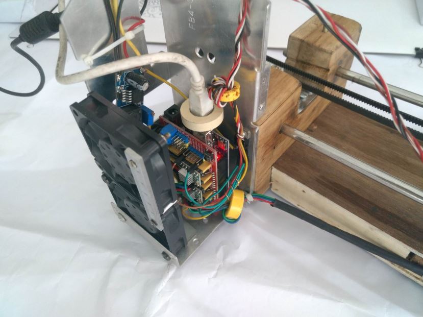 Arduino UNO With BLDC Fans and Stepper Driver
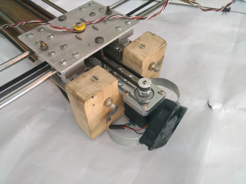 Stepper Motor With BLDC Fan
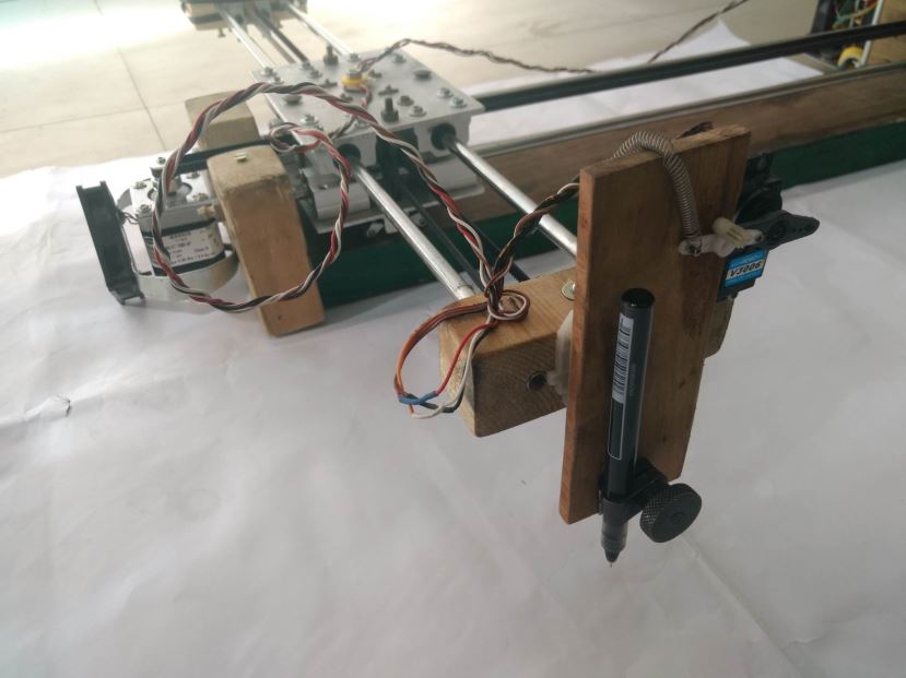 Pen Holder
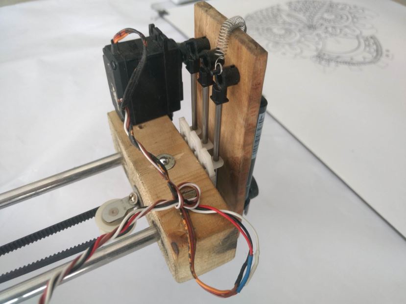 Pen Holder WIth Servo Motor
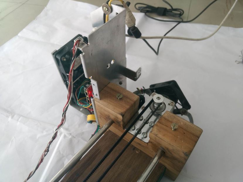 Back Side of Heat Sink
Arduino Firmware Installation
This project is using a modified version of GRBL 0.9i Firmware that
You Can Download my modified firmware from Git: https://github.com/arnabdasbwn/grbl-coreXY-servo
Grbl-coreXY-servo is a no-compromise, high performance,
The controller is written in highly optimized C utilizing every clever feature of the AVR-chips to achieve precise timing and asynchronous operation. It is able to maintain up to 30kHz of stable,
It accepts standards-compliant G-Code and has been tested with the output of several CAM tools with no problems. Arcs, circles and helical motion are fully supported, as well as, all other primary G-Code commands. Macro functions, variables, and most canned cycles are not supported, but we think GUIs can do a much better job at translating them into straight G-Code anyhow.
Grbl-coreXY-servo includes full acceleration management with
• Licensing: Grbl is free software, released under the GPLv3 license.
After downloading you have to flash the Arduino Uno with the firmware.
Here are the Steps:
NOTE: Before starting, delete prior Grbl library installations from the Arduino IDE. Otherwise, you'll have compiling issues! On a Mac, Arduino libraries are located in ~/Documents/Arduino/libraries/. On Windows, it's in My Documents\Arduino\libraries.
1. Download from https://github.com/arnabdasbwn/grbl-coreXY-servo the ZIP File
• Unzip the download and you'll have a folder called
2. Launch the Arduino IDE
• Make sure you are using the most recent version of the Arduino IDE!
3. Load Grbl into the Arduino IDE as a Library
• Click the Sketch drop-down menu, navigate to Include Library and select
• IMPORTANT: Select the Grbl folder inside the
• If you accidentally select the .zip file or the wrong folder, you will need to navigate to your Arduino library, delete the mistake, and re-do Step 3.
4. Open the GrblUpload Arduino example
• Click the File down-down menu, navigate to Examples->Grbl, and select GrblUpload.
5. Compile and upload Grbl-coreXY-servo to your Arduino
• Connect your Arduino Uno to your computer.
• Make sure your board is set to the Arduino Uno in the Tool->Board menu and the serial port is selected correctly in Tool->Serial Port.
• Click the Upload, and Grbl-coreXY-servo should compile and flash to your Arduino! (Flashing with a programmer also works by using the Upload Using Programmer menu command.)
Software Tools Installation
We need multiple software and plugins for generating art-work, editing and sending G-Code to the CNC using Serial COM Port. I will be discussing installation in Windows platform but you can find all the software for
>>> Inkscape
[ Will be used to edit vector graphics and also to generate vector graphics (.svg) from .jpg, .png and .dxf formats ]
• Download the latest stable 32bit/64bit version according to your OS from Inkscape.org
• Installation is pretty simple and straight forward in Windows. In
• Just do a Next Next and software will be installed.
>>> JTP Laser Tool Inkscape Plugin
[This Inkscape plugin will convert paths/drawing to G-Code for Vector Printing]
• Download the plugin from JTP Website
• Extract it using any good unzipping software.
• Put the contents of this .zip folder into the “inkscape\share\extensions” folder in
• Once it is there it will show up under the “extensions” tab in Inkscape.
>>> Raster 2 Laser G-Code Generator
[This Inkscape plugin will convert paths/drawing to G-Code for Raster Printing]
• Download the plugin from my Git Hub Repository Raster 2 Laser
• Extract it using any good unzipping software.
• Put the contents of this .zip folder into the “Inkscape\share\extensions” folder in
• Once it is there it will show up under the “extensions” tab in Inkscape.
>>> UGS Platform / UniversalGcodeSender
[ Will send G-Codes from laptop to Arduino UNO via USB Serial Port]
• Download and install the version of Java listed on the download page according to your OS and system configuration. Requires Java 8. Download Here
• Download UGS Platform UGS Download
• Extract it using any good unzipping software.
• In the extracted folders locate bin in the ugsplatform directory.
• On Windows run ugsplatform.exe or ugsplatform64.exe, on Linux or Mac OSX run ugsplatform.
• No need of any installation or build.
>>> Camotics
[ Will be used for visualizing G-Codes and simulation purpose]
• Download the latest version from Camotics
• Simple and fluid installation.
>>> Makelangelo Software
[Will be used to
• Download the Makelangelo Software from my Git Hub Repository Makelangelo-Software
• Extract it using any good unzipping software.
• Open the extracted folder and find Makelangelo10.jar file.
• Run the .jar file using Java 8 you have installed in previous steps.
>>> Inkscape Template File
[This template will be used according to the paper
• Download the template from my Git Hub Repository Inkscape-Template
• Extract it using any good unzipping software.
• Open the extracted folder and find Makelangelo10.jar file.
Processing from Existing JPG/PNG Image in Inkscape
• Open Inkscape.
• Open the template you have downloaded in
• Click on File -> Import then select the JPG or PNG file from your drive and click open.
• Resize and position the image according to your page size.
•
•
• Select any of the Three Option [ Experiment and You will know the working] Brightness Cutoff, Edge Detection, Colour Quantization.
• Change the threshold according to the details you want in the drawing.
• Click on Update.
• Click OK and close the window.
• The Vector Bitmap will be overlapping the original picture.
• Drag out the original picture and delete it. You are ready to generate G-code.
• Now See G-code Generation Step.
Processing from Custom Drawing in Inkscape
• Open Inkscape.
• Open the template you have downloaded in
• Start drawing or writing text inside the work area.
• Select all the objects by Ctrl+A shortcut.
• Group then together by Object -> Group from
• Then you have to convert
• Now See G-code Generation Step.
Generating Art Work from Image in Makelangelo Software
• Open Makelangelo Software running the .jar file.
• Click Open File and select the JPG/PNG file from your drive.
• Select the Conversion Style from the drop down menu. [ My fav is Crosshatch]
• Click ok.
• Click Save to file/SD Card and go to the location where you want to save.
• Put your file name and select DXF R12 File Format .DXF.
• Now run Inkscape and open the saved .DXF file with default settings.
• Resize it according to your need.
• Now See G-code Generation Step.
Raster G-code Generation
• In raster
• After converting all objects to
• Now select all the paths that are inside the work area or use Ctrl+A.
• Click Extensions -> 305 Engineering -> Raster 2 Laser G-code Generator.
• Give Export Directory Path.
• Give File Name.
• Enable Numeric Suffix.
• Resolution means
• Play with the options below like the RGB threshold.
• Set Engraving speed to 1500 or above.
• Select No Homing.
• Edit Laser ON to M03 S255.
• Edit Laser OFF to M05 S0.
• Deselect Preview, if selected no G-code will be generated.
• Click Apply. Wait and Enjoy. You are Ready to print now.
Vector G-code Generation
• In vector
• After converting all objects to
• Now select all the paths that are inside the work area or use Ctrl+A.
• Click Extensions -> Generate laser G-code -> J Tech Photonics Laser Tool.
• Give Export Directory Path.
• Give File Name.
• Enable Numeric Suffix.
• Set All Units to mm.
• Set Laser speed to 1500 or above.
• Set Travel speed to 3000 or above.
• Select No Homing.
• Edit Laser ON to M03.
• Edit Laser OFF to M05.
• Deselect Preview
• Click Apply. Wait and Enjoy. You are ready to Print now.
GRBL Configuration and Setting Up Your Machine for the First Time
First, connect to Grbl using the serial terminal of your choice.
Set the baud rate to 115200 as 8-N-1 (8-bits, no parity, and
Once connected you should get the Grbl-prompt, which looks like this:
Grbl 0.9i ['$' for help]
Type $ and press enter to have Grbl print a help message. You should not see any local echo of the $ and enter. Grbl should respond with:
[HLP:$$ $# $G $I $N $x=val $Nx=line $J=line $SLP $C $X $H ~ ! ? ctrl-x]
The ‘$’-commands are Grbl system commands used to tweak the settings, view or change Grbl's states and running modes, and start a homing cycle. The last four non-'$' commands are realtime control commands that can be sent at
$$ - View Grbl settings
To view the settings, type $$ and press enter after connecting to Grbl. Grbl should respond with a list of the current system settings, as shown in the example below. All of these settings are persistent and kept in EEPROM, so if you power down, these will be loaded back up the next time you power up your Arduino.
$x=val - Save Grbl setting
The $x=val command saves or alters a Grbl setting, which can be done manually by sending this command when connected to Grbl through a serial terminal program, but most Grbl GUIs will do this for you as a user-friendly feature.
To manually change e.g. the microseconds step pulse option to 10us you would type this, followed by an
$0=10
If everything went well, Grbl will respond with an 'ok' and this setting is stored in EEPROM and will be retained forever or until you change them. You can check if Grbl has received and stored your setting correctly by typing $$ to view the system settings again.
Grbl's default configuration is intentionally very generic to help ensure users can see successful motion without having to tweak settings. Generally, the first thing you'll want to do is get your stepper motors running, usually without it connected to the CNC. Wire Grbl to your stepper drivers and stepper motors according to your manufacturer guidelines. Connect to Grbl through a serial terminal or one of many Grbl GUIs. Send some G1 or G0 commands to Grbl. You should see your stepper motor rotating. If you are having trouble with your stepper motors, try the following:
• Ensure everything is wired and powered correctly per your stepper driver manufacturer guidelines.
• If your steppers are mounted in your CNC already, ensure your axes move freely and don't obviously bind. If you can't easily tell, try removing your steppers and check if they run under no load.
• Ensure your stepper motors and axes linear mechanisms are all tight and secure. Small set screws on drivetrain components becoming loose is a very common problem. Re-tighten and try applying some non-permenant thread locker (Loctite blue) if it continually loosens.
• For more difficult issues, try the process of elimination to quickly isolate the problem. Start by disconnecting everything from the Arduino. Test if Grbl is operating ok by itself. Then, add one thing at a time and test.
• If your steppers are powered and making a grinding noise when trying to move, try lowering the '$' acceleration and max rate settings. This sound is a sign that your steppers
• Grbl's default step pulse settings cover the vast majority of stepper drivers on the market. While very uncommon, check these settings if you are still experiencing problems or have
Next, you will need to make sure your machine is moving in the correct directions according to a Cartesian(XYZ) coordinate frame. Mount your stepper motors into your CNC, if you haven't already done so. Send Grbl some motion commands, such as G91 G0 X1 or G91 G0 X-1, which will move the x-axis +1mm and -1mm, respectively. Check all axes. If an axis is not moving correctly, alter the $3 direction port mask setting to invert the direction.
If you are unfamiliar with how coordinate frames are setup on CNC machines, see this great diagram by LinuxCNC. Just keep in mind that motions are relative to the tool. So on a typical CNC gantry router, the tool will move rather than the fixed table. If the x-axis is aligned positive to the right, a positive motion command will move the tool to the right. Whereas, a moving table with a fixed tool will move the table to the left for the same
Finally, tune your settings to get close to your desired or max performance. Start by ensuring your $100,$101, and $102 axes step/mm settings are correct for your setup. This is dependent on your stepper increments, micro steps on your driver, and mechanical parameters. There are multiple resources online to show you how to compute this for your particular
At this point, you're pretty much ready to get going! Grbl can now move your CNC machine and
Here is my Setting
$0 = 10 (step pulse, usec)
$1 = 25 (step idle delay, msec)
$2 = 0 (step port invert mask:00000000)
$3 = 0 (dir port invert mask:00000000)
$4 = 0 (step enable invert, bool)
$5 = 0 (limit pins invert, bool)
$6 = 0 (probe pin invert, bool)
$10 = 3 (status report mask:00000011)
$11 = 0.010 (junction deviation, mm)
$12 = 0.010 (arc tolerance, mm)
$13 = 0 (report inches, bool)
$20 = 0 (soft limits, bool)
$21 = 0 (hard limits, bool)
$22 = 0 (homing cycle, bool)
$23 = 0 (homing dir invert mask:00000000)
$24 = 25.000 (homing feed, mm/min)
$25 = 500.000 (homing seek, mm/min)
$26 = 250 (homing debounce, msec)
$27 = 1.000 (homing pull-off, mm)
$100 = 80.000 (x, step/mm)
$101 = 80.000 (y, step/mm)
$102 = 80.000 (z, step/mm)
$110 = 5000.000 (x max rate, mm/min)
$111 = 5000.000 (y max rate, mm/min)
$112 = 5000.000 (z max rate, mm/min)
$120 = 50.000 (x accel, mm/sec^2)
$121 = 50.000 (y accel, mm/sec^2)
$122 = 30.000 (z accel, mm/sec^2)
$130 = 310.000 (x max travel, mm)
$131 = 450.000 (y max travel, mm)
$132 = 200.000 (z max travel, mm)
Results
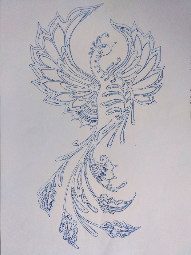 Vector Drawing Crazy Engineer’s Drawbot
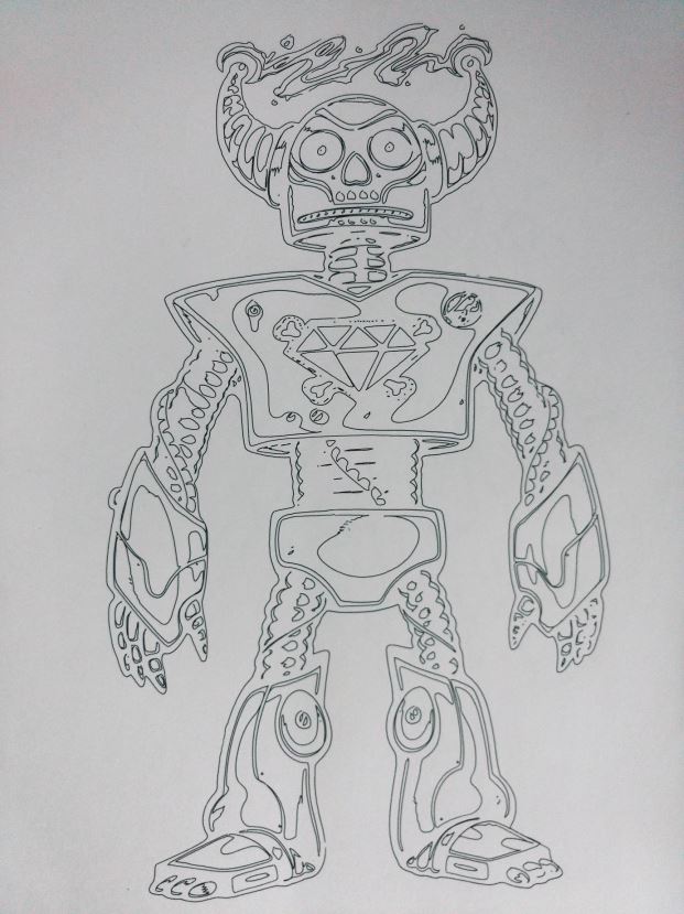 Vector Drawing Crazy Engineer’s Drawbot
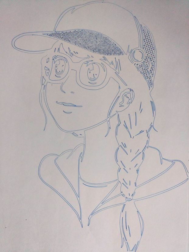 Vector Drawing Crazy Engineer’s Drawbot
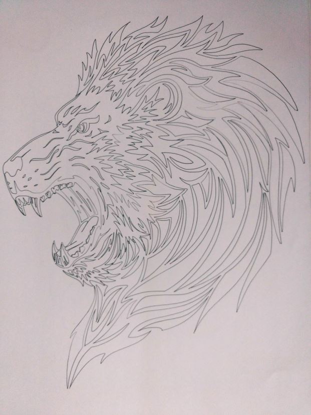 Vector Drawing Crazy Engineer’s Drawbot
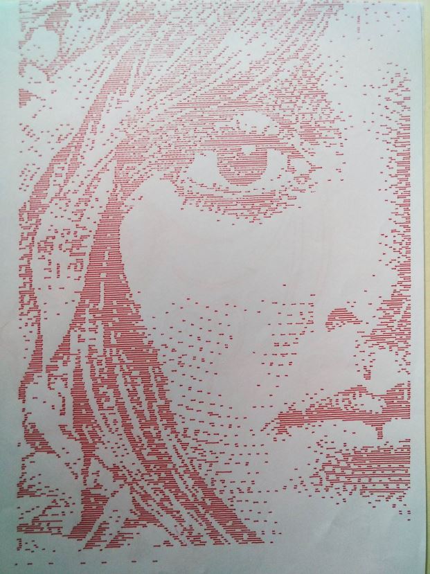 Raster Drawing Crazy Engineer’s Drawbot
 Vector Text Crazy Engineer’s Drawbot
 Vector Drawing Crazy Engineer’s Drawbot
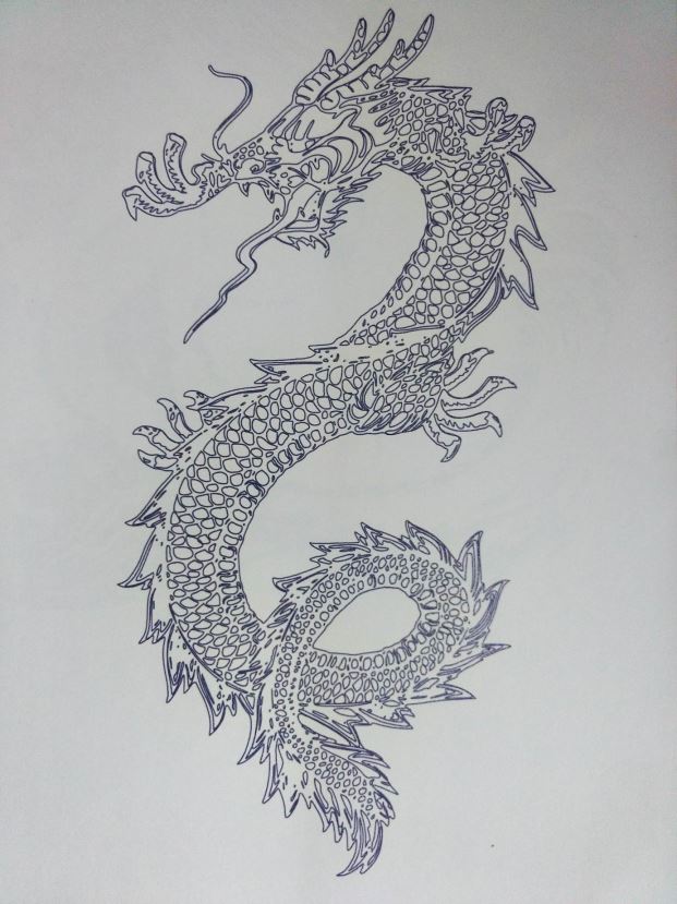 Vector Drawing Crazy Engineer’s Drawbot
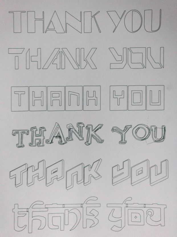 Vector Text Crazy Engineer’s Drawbot
 Vector Drawing Crazy Engineer’s Drawbot
 Raster Drawing Crazy Engineer’s Drawbot
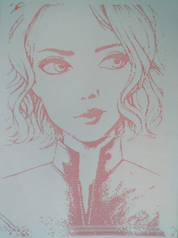 Raster Drawing Crazy Engineer’s Drawbot