Introduction
Line Follower Robot or Line Tracer Robot or Robot Tracer is an Autonomous Robot that follows a visual or magnetic line painted or embedded in the surface of locomotion. Line Follower Robot is a category of a mobile robot that is capable of moving in a surrounding relying on guidance devices that allow them to travel a pre-defined navigation route in relatively controlled space. Some of the Automated Guided Vehicles (AGVs) use magnetic or colour tape for the guide path and are usually used in warehouses for autonomously sorting/loading storage racks.
Line Follower Robots is a great project for anyone taking the first steps of robotics. Line Follower Robot / Line Tracer Robot project gives a detailed understanding of every component of a mobile robot such as controller, sensors, actuators, power system, and algorithm. The controller is generally a microprocessor or microcontroller. Sensors depend on the requirements and available input parameters. Actuators usually refer to the motors that move the robot. The power system in a mobile robot is usually DC and provided from a battery. The algorithm depends on the application and requirements of the mobile robot.
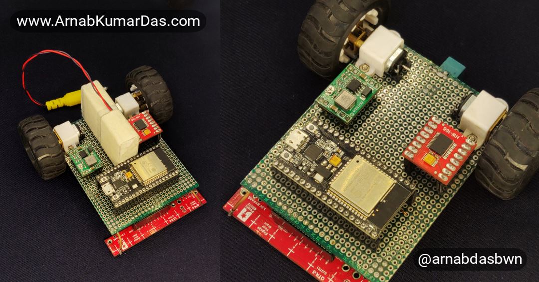
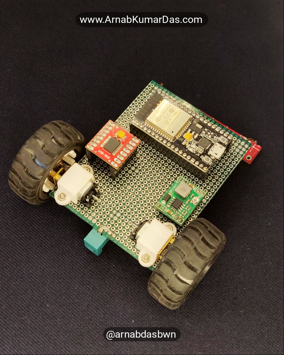
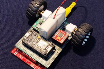
In this tutorial we will make a 10.5cm x 10.5cm Line Follower Robot using ESP32 as the controller, QTR-8RC as the sensor, N20 300RPM 12V DC Gear Motor as the actuator, 12V Li-Ion Battery with DC-DC converter as the power system, and PID based control system as the algorithm to follow the line. The Firmware Code of this project is available for Arduino IDE.
What You Will Learn
- How to make an ESP32 PID Control System based Line Follower Robot?
- How PID works in ESP32 Line Follower Robot?
- How to interface and use QTR-8RC with ESP32?
- How QTR-8RC Sensor is Interfaced with ESP32 Line Follower Robot?
Prerequisite
- Knowledge of C Programming
- Background knowledge of ESP32
- Background knowledge of GPIO
- Background knowledge of TIMER
- Basic knowledge of Electronics
Hardware Bill of Materials
- Pololu QTR-8RC Line Sensor – 1pc
- ESP32 Node MCU – 1pc
- TB6612FNG Motor Driver – 1pc
- MP1584 DC-DC Converter – 1pc
- Perf Board 7cm x 9cm – 1pc
- DC Barrel Connector Male – 1pc
- DC Barrel Connector Female – 1pc
- BL-5C / BL-4C Li-Ion Battery – 3pcs
- N20 Gear Motor 12V 300RPM – 2pcs
- N20 Motor Wheel 43mm – 2pcs
- N20 Motor Bracket – 2pcs
- Small Caster Wheel – 1pc
- Nut and Bolt – 6pcs
- 0.5mm Wire
- Black Tape
- White Tape
- Tools
Software Bill of Materials
Hardware Description
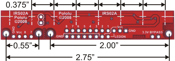
Pololu QTR-8RC Line Sensor

The QTR-8RC is a reflectance sensor array designed primarily to be used as a line sensor for line follower robots. QTR-8RC has eight IR emitter and receiver (phototransistor) pairs evenly spaced at intervals of 0.375″ (9.525 mm). The sensor can be split into two parts if needed. The QTR sensor has eight infrared emitter/receiver that is able to differentiate between a dark surface) with low IR reflectivity) and a light surface (with high IR reflectivity).
What does QTR stand for?
- Q = Charge
- T = Transfer
- R = Resistance

Each sensor unit has a 10nF capacitor in series with a QRE1113GR phototransistor. One end of the capacitor is connected to VCC and another end of the phototransistor is connected to GND. The junction between the capacitor and the phototransistor is connected to a GPIO of a microcontroller via a 220Ω resistor and is the OUT pin.
The phototransistor is like a transistor and a transistor is like a valve that regulates the amount of electric current that passes through two of its three terminals. The third terminal controls just how much current passes through the other two. Depending on the type of transistor, the current flow can be controlled by voltage, current, or in the case of the phototransistor, by light and acts as the third terminal. In the case of the QTR sensor, the light is Infrared (IR).
The Pololu QTR uses a QRE1113GR infrared (IR) reflective sensor to determine the reflectivity of the surface below it. When the sensor is over a black surface, the reflectivity is very low; when the QTR is over a white surface, the reflectivity is very high and will cause a different reading from the sensor.

The QTR sensor is activated by placing 3.3V on the VCC pin. When the LEDON pin is HIGH (3.3V) it will cause a current to flow through the 47Ω resistor to the LED side of the QRE1113GR. IR light reflecting off the surface below will cause a change in the ability for current to flow through the phototransistor side of the QRE1113GR. The transistor, in effect, behaves like an IR controlled resistance.
When the QTR is powered, the OUT pin is kept at HIGH. Both the terminal of the capacitor gets shorted to VCC and the capacitor discharges through the 220Ω resistor with a time constant of 2.2us. Holding the GPIO to HIGH for about 10us ensures it is completely discharged.
After the capacitor is discharged the microcontroller’s GPIO connected to the OUT pin is made into High Impedance Input. As soon as the pin becomes input the capacitor starts charging. The timer in the microcontroller is then used to measure the time required to charge the capacitor to a specified level. When the charge in the capacitor increases the voltage drop across it increases and the voltage at the OUT pin decreases. At full charge, the voltage at the OUT pin becomes nearly zero (LOW). This timing will be controlled by the current flowing through the phototransistor side of the QRE1113GR. When over a black surface, the phototransistor current flow will be very low so the capacitor will take a long time to charge. When the QTR is positioned over a white surface, the current flow through the phototransistor is high, so the capacitor charge time is fast.
ESP32 Node MCU Board
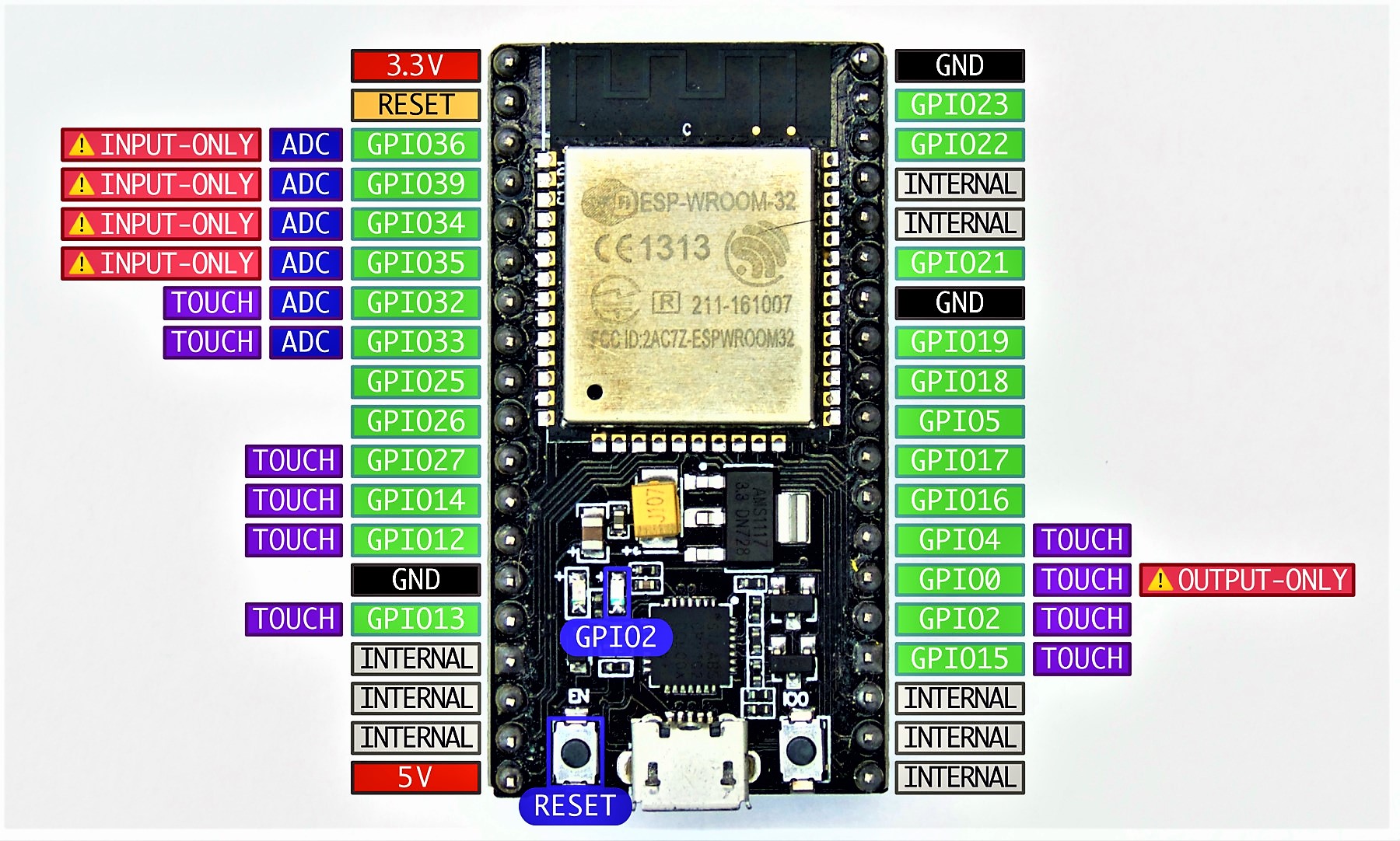
Specification of NodeMCU ESP32
| Microcontroller | ESP32 ( |
| Operating Voltage | 3.3V |
| Flash Memory | 4MB |
| SRAM | 512KB |
| Clock Speed | 240MHz |
| Analog IN Pins | 5 |
| Digital I/O Pins | 24 (Usable) |
| PCB Size | 25mm x 50mm |
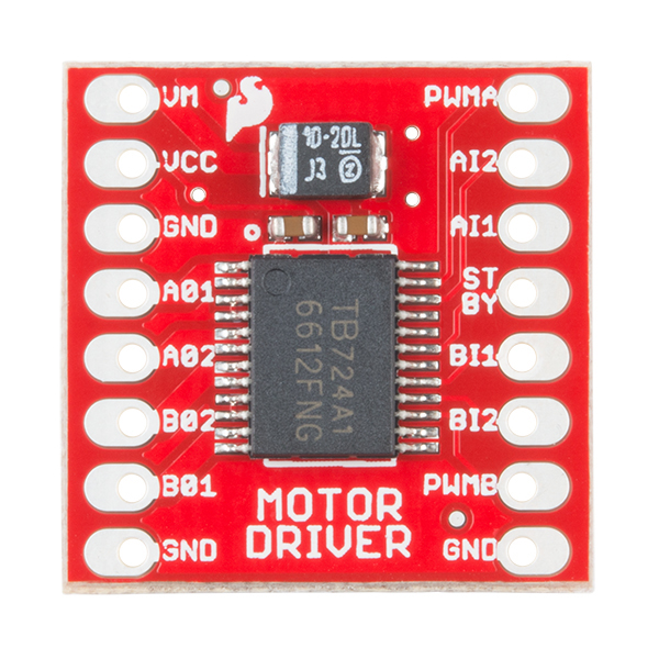
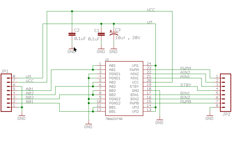
TB6612FNG Motor Driver
TB6612FNG is a DC Motor Driver IC with can control up to two DC motors at a constant current of 1.2A (3.2A peak). Two input signals, IN1 and IN2 can choose one of four modes such as CW, CCW, short brake, and stop mode.
The two motor outputs (A and B) can be separately controlled, and the speed of each motor is controlled via a PWM input signal with a frequency up to 100kHz. The STBY pin should be pulled high to take the motor out of standby mode.
Specification of TB6612FNG
| Supply Voltage VM (Motor) | 4.5 – 13.5V |
| Supply Voltage Vcc | 2.7 – 5.5V |
| Input Voltage VIN | 3.3V / 5V (IN1, IN2, STBY, PWM) |
| Current Per Channel | 1.2A |
| Current Per Channel Peak Pulse | 3.2A |
| PCB Size | 20mm x 20mm |
TB6612FNG Pin Operation Logic
| IN1 | IN2 | PWM | STBY | OUT1 | OUT2 | Mode |
|---|---|---|---|---|---|---|
| H | H | H/L | H | L | L | Short Brake |
| L | H | H | H | L | H | CCW |
| L | H | L | H | L | L | Short Brake |
| H | L | H | H | H | L | CW |
| H | L | L | H | L | L | Short Brake |
| L | L | H | H | OFF | OFF | Stop |
| H/L | H/L | H/L | L | OFF | OFF | Standby |
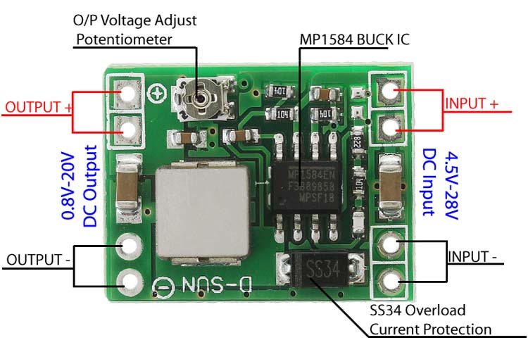
MP1584 DC-DC Converter
The MP1584 is a high frequency step-down switching regulator with an integrated internal high-side high voltage power MOSFET. It provides 3A output with current mode control for fast loop response and easy compensation. The wide 4.5V to 28V input range accommodates a variety of step-down applications. High power conversion efficiency over a wide load range is achieved by scaling down the switching frequency at light load conditions to reduce the switching and gate driving losses. The frequency foldback helps prevent inductor current runaway during startup and thermal shutdown provides reliable and fault tolerant operation. By switching at 1.5MHz, the MP1584 is able to prevent EMI (Electromagnetic Interference) noise problems. The PCB size is 22mm x 17mm. This DC-DC converter module will be used
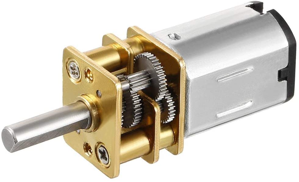
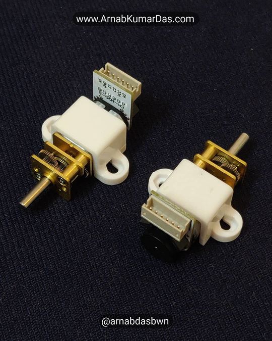
N20 Micro Geared Motor
N20 12V 300RPM Micro Geared Motor is a tiny motor having a gear ratio of 1:100 is a lightweight high torque motor suitable for a variety of industrial, home appliances, and hobby applications. As compared to other motors of this size either with metal or plastic gears, the N20 metal geared motor has a much higher torque to size ratio.
N20 12V 300RPM Micro Geared Motor Specification
| Supply Voltage | 12V |
| Gear Ratio | 100:1 |
| No Load Speed @ 12V | 300 RPM |
| No Load Current @ 12V | 0.06A |
| Stall Current @ 12V | 0.75A |
| Stall Torque @ 12V | 1.3 kg-cm |
| Size | 10mm × 12mm × 26 mm |

Circuit Design
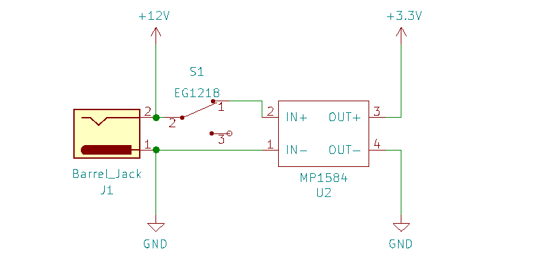
Power System Design
The ESP32 Line Follower Robot has two types of components in it, one working at 3.3V and another at 12V. The microcontroller, sensor, and motor driver run at 3.3V. Whereas the motors work at 12V. MP1584 DC-DC converter provides a 3.3V constant voltage power supply from a 3S Li-Ion battery pack. The battery connects to the ESP32 Line Follower Robot via a DC barrel connector. The battery pack provides 12.6V when full charge and 11.1V when fully discharged. The DC-DC converter ensures that constant voltage is always generated at the highest efficiency. The motors get directly connected to the Li-Ion battery pack.
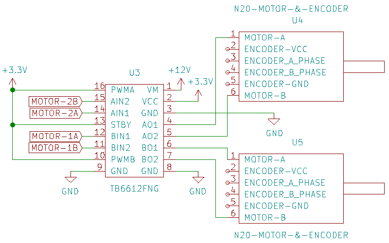
Actuator Design
The ESP32 Line Follower Robot uses two N20 12V 300RPM motors for locomotion. The motors run directly at the battery voltage 11.1V – 12V. The motor driver TG6612FNG runs at 3.3V. The PWMA, PWMB, STBY pins are directly pulled to 3.3V to keep the driver enabled all the time. This design is chosen to reduce the number of GPIO needed to control the motors. MOTOR-1B and MOTOR-1A pins are responsible for controlling the speed and direction of motor M1/U4. MOTOR-2B and MOTOR-2A pins are responsible for controlling the speed and direction of motor M2/U5. All four pins are directly connected to the microcontroller’s PWM pins.
Both the motors combined can drive the Line Follower Robot in straight, reverse, or turning paths.
| Left Motor | Right Motor | Robot Movement |
| Straight | Straight | Straight |
| Stop | Straight | Left |
| Reverse | Straight | Sharp left |
| Straight | Stop | Right |
| Straight | Reverse | Sharp Right |
| Reverse | Reverse | Reverse |
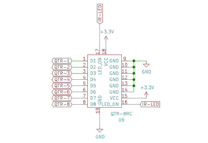
Sensor Design
The ESP32 Line Follower Robot uses one QTR-8RC sensor for line sensing. The QTR-8RC sensor operates at 3.3V and gets connected to the 3.3V output of the DC-DC converter. The QTR-8RC has eight sensor outputs, one for each IR sensor. The sensor outputs QTR-1 to QTR-6 go to the microcontroller’s GPIO. IR-LED is an input pin for the QTR-8RC and it controls the IR LED in each of the sensors. IR-LED pin also connects to the microcontroller’s GPIO.
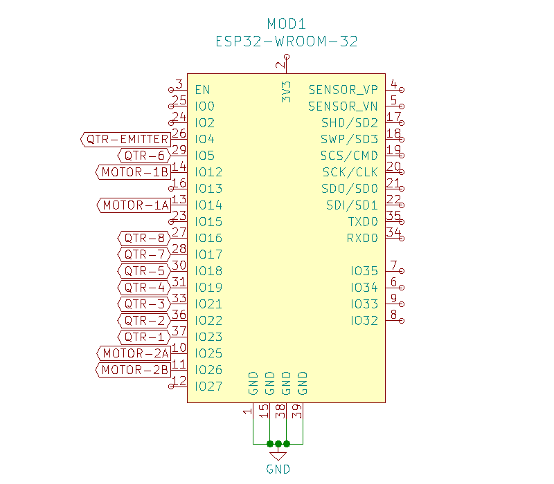
Microcontroller Design
The Line Follower Robot uses an ESP32 NodeMCU board as the control unit. ESP32 has all the required components to run an onboard ESP32 microcontroller. NodeMCU runs at 3.3V and is connected to the DC-DC converter’s 3.3V output. Motor pins are connected to PWM capable GPIOs and the Sensor pins are connected to digital GPIO.
Making the Line Follower Robot
- Gather the required material as mentioned in the bill of materials section
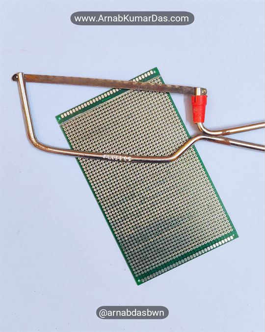
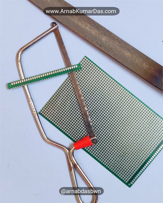
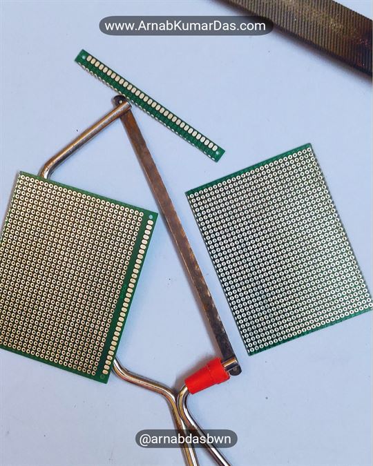
STEP 1
- The first step is to make a chassis out of perf board / Zero PCB that will support every other components
- The perf board need to be cut to the size 7cm x 9cm or alternatively you can use a perf board of the right size
- Use a file to smoothen the edges of the Zero PCB / perf board
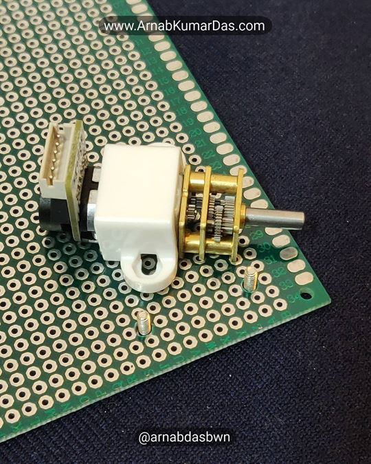
STEP 2
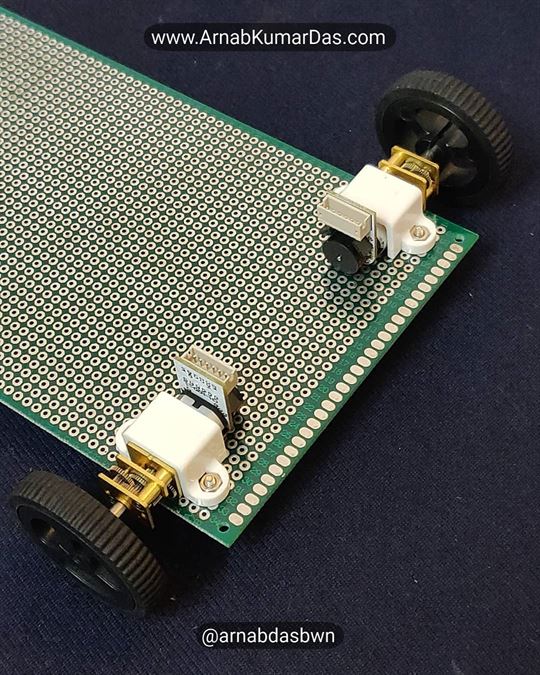
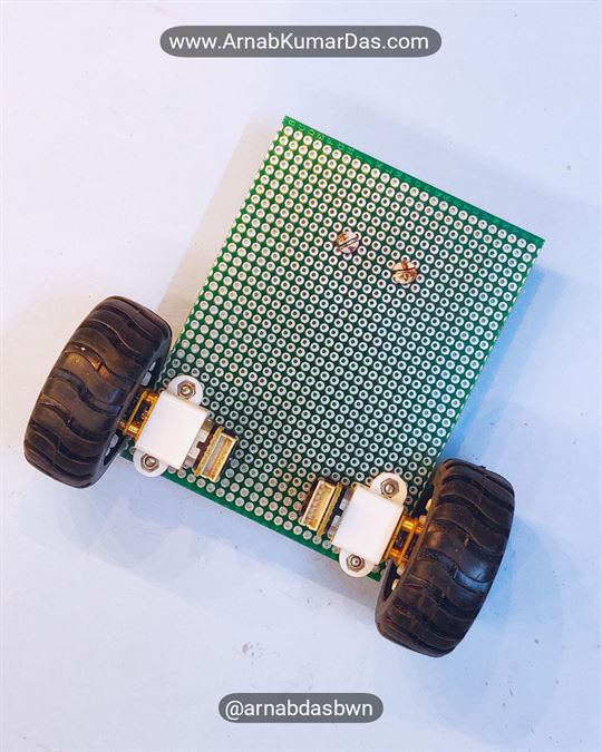
- The second step is to mount the N20 motors to the chassis
- Both the motor should be in straight line and perpendicular to the longer edge of the chassis
- Use the N20 motor’s mounting bracket to position the drill holes needed for mounting the motors

STEP 3
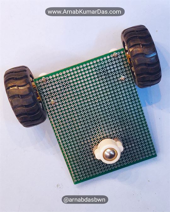
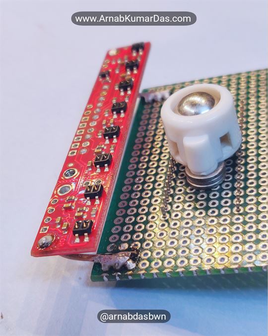
- The caster wheel need to be mounted exactly at the center line between both the motors
- The center point of the caster wheel and both the motor should form a isosceles triangle
- The height of the caster wheel should be same as that of the wheel, such that the chassis stays parallel to the surface
- The ball in the caster should be able to move freely in all direction
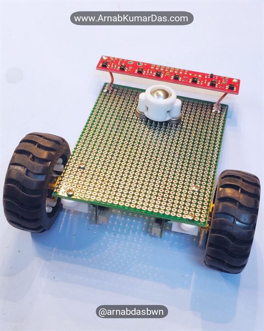
STEP 4
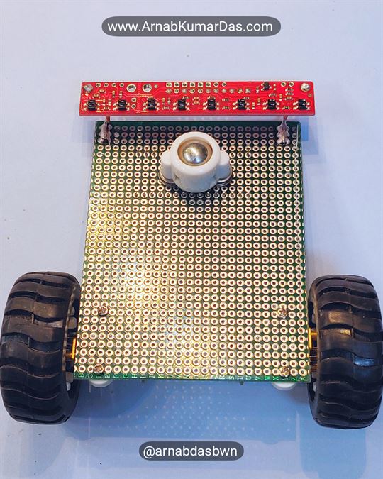
- The fourth step is to mount the QTR-8RC sensor to the chassis
- The sensor should to be mounted in such a way that the space between the sensor and the surface of locomotion should not be more than 3mm
- The sensor should be parallel to the surface of locomotion
- The sensor should also be paralle to the straight line connecting both the motors
STEP 5
- The fifth step is to mount the NodeMCU ESP32 to the chassis
- The NodeMCU ESP32 should be mounted in such a way that the distance between the sensor and the ESP32 is minimal
- 2.54mm header can be used for easy removal of the NodeMCU ESP32 board
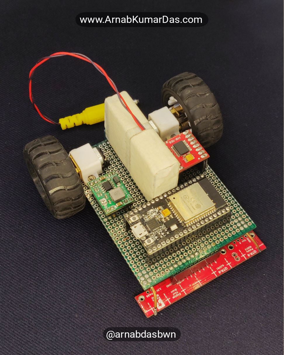
STEP 6
- The sixth step is to mount the other electronics and modules to the chassis
- Keep a gap between the components to make space for the battery
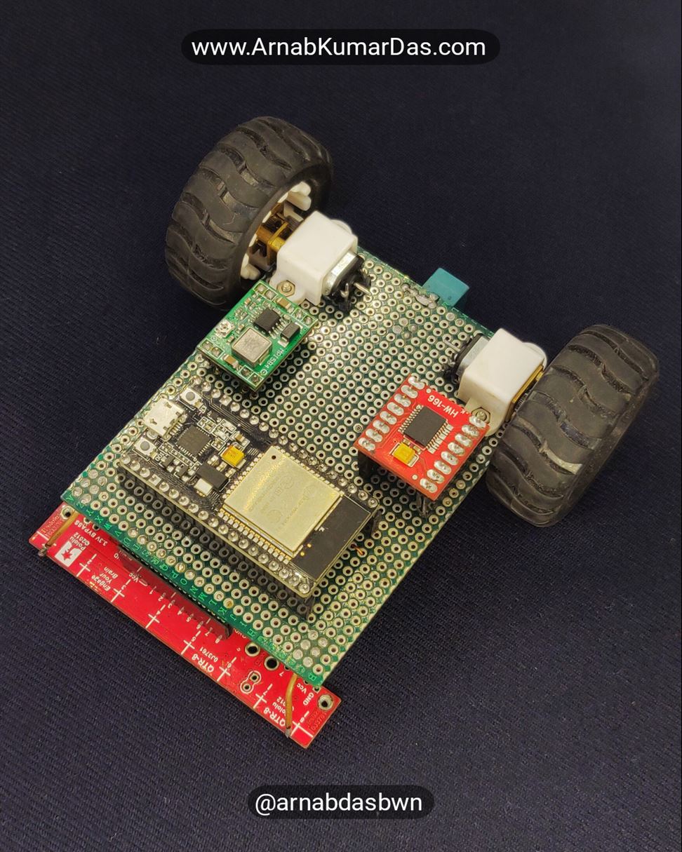
STEP 7
- The seventh step is to connect every components together
- Use the schematic provided to connect the sensor, microcontroller and motor together
- Try to keep the connection in only one side of the PCB
Line Follower Robot PID Control System Concept
A control system manages, commands direct, or regulates the behaviour of other devices or systems using control loops. It can range from a single home heating controller using a thermostat controlling a domestic boiler to large industrial control systems which are used for controlling processes or machines.
There are two common classes of control action: open loop and closed loop. In an open-loop control system, the control action from the controller is independent of the process variable. An example of this is a central heating boiler controlled only by a timer. The control action is the switching on or off of the boiler. The process variable is the building temperature. This controller operates the heating system for a constant time regardless of the temperature of the building.
In a closed-loop control system, the control action from the controller is dependent on the desired and actual process variable. In the case of the boiler analogy, this would utilize a thermostat to monitor the building temperature, and feedback a signal to ensure the controller output maintains the building temperature close to that set on the thermostat. A closed-loop controller has a feedback loop which ensures the controller exerts a control action to control a process variable at the same value as the setpoint. For this reason, closed-loop controllers are also called feedback controllers.
In the case of linear feedback systems, a control loop including sensors, control algorithms, and actuators is arranged in an attempt to regulate a variable at a setpoint (SP). In the case of Line Follower Robot, the sensor is the QTR-8RC line sensor and the control algorithm runs inside the microcontroller i.e ESP32 and the setpoint is the position of the line at the centre of the robot. The PID algorithm in the controller restores the actual speed to the desired speed in an optimum way, with minimal delay or overshoot, by controlling the power/speed output of the vehicle’s motor.
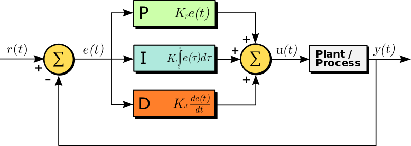
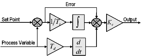
A Proportional Integral Derivative Controller (PID Controller) is a control loop mechanism employing feedback that is widely used in industrial control systems and a variety of other applications requiring continuously modulated control. A PID controller continuously calculates an error value e(t) as the difference between a desired setpoint (SP)=r(t) and a measured process variable (PV)=y(t), error value e(t)=r(t)-y(t). The PID controller applies a correction based on proportional, integral, and derivative terms (denoted P, I, and D respectively). The controller attempts to minimize the error over time by adjustment of a control variable u(t).
In the case of the Line Follower Robot, the r(t) is the desired setpoint to keep the line always in the centre of the robot. The error e(t) is the difference between the actual position of the robot y(t) and the desired position of the robot r(t). u(t) is the output of the algorithm to control the motor.
The term P is proportional to the current value of the error e(t). For example, if the error is large and positive, the control output will be proportionately large and positive, taking into account the proportional gain factor Kp. Using proportional control alone will result in an error between the setpoint and the actual process value because it requires an error to generate the proportional response. If there is no error, there is no corrective response.
In the Line Follower Robot, the difference in the position of the line at the centre of the robot r(t) and the actual position gives the e(t). The positional error e(t) is calculated using the QTR-8RC line sensor and its data acquisition algorithm. The error e(t) gets multiplied with Kp and forms the proportional output of the controller. More the value of Kp more strong is the output. The robot tends to be more responsive with a higher value of Kp. Too much high Kp can lead to overshoots and the robot can lose the line.
The term I account for past values of the error e(t) and integrates them over time to produce the I term. For example, if there is a residual e(t) error after the application of proportional control, the integral term seeks to eliminate the residual error by adding a control effect due to the historic cumulative value of the error. When the error is eliminated, the integral term will cease to grow. This will result in the proportional effect diminishing as the error decreases, but this is compensated for by the growing integral effect. The integral gain factor Ki will determine how fast the integral value accumulates.
In the Line Follower Robot, the positional error e(t) gets multiplied with Ki and forms the integral output of the controller. The result is that even a small error term will cause the integral component to increase slowly. The integral output will continually increase over time unless the error is zero i.e the robot is aligned properly on the line.
The term D is the best estimate of the future trend of the error e(t), based on its current rate of change. It is effectively seeking to reduce the effect of the error e(t) by exerting a control influence generated by the rate of error change. The more rapid the change, the greater the controlling or damping effect. The derivative gain factor Kd will determine how fast the damping effect applies.
The derivative component causes the output to decrease if the process variable is increasing rapidly, i.e if the Line Follower Robot wobbles The derivative response is proportional to the rate of change of the process variable. Increasing the Kd parameter will cause the Line Follower Robot to react more strongly to changes in the error term and will increase the speed of the overall control system response. It is advised to use a very small derivative gain Kd because the derivative response is highly sensitive to noise in the process variable signal. If the sensor signal is noisy or if the control loop rate is too slow, the derivative response can make the Line Follower Robot unstable.
Line Follower Robot PID Tuning
The process of setting the optimal gains for Kp, Ki, and Kd to get an ideal response/performance from a Line Follower Robot/control system is called tuning.
Trial and Error Method
The gains of a PID controller can be obtained by the trial and error method. Once you understand the significance of each gain parameter, this method becomes relatively easy.
In this method, the Ki and Kd terms are set to zero first and the proportional gain Kp is increased until the Line Follower Robot starts to oscillate/wobble. As the proportional gain is increased, the system / Line Follower Robot becomes faster, but care must be taken as too much can make the system unstable and the robot will miss the line. The goal is to get the robot to follow the line even if it is very wobbly. If the robot overshoots and loses the line, reduce the Kp value. If the robot cannot navigate a turn or seems sluggish, increase the Kp value.
Once Kp has been set to obtain a desired fast response, the integral gain Ki is increased to stop the oscillations/wobbling. The integral term reduces the steady-state error but increases overshoot. Some amount of overshoot is always necessary for a fast system so that it could respond to changes immediately. The integral term is tweaked to achieve a minimal steady-state error.
Once the Kp and Ki have been set to get the desired fast line following with minimal steady-state error/wobbles, the derivative term Kd is increased until the Line Follower Robot is acceptable returns quickly to its set point. Increasing derivative term decreases overshoot and yields higher gain with stability but would cause the system to be highly sensitive to noise.
You need to tradeoff one characteristic of a PID Line Follower Robot for another to better meet the requirements.
Ziegler Nichols Method
The Ziegler Nichols method is another popular method of tuning a PID controller or Line Follower Robot. It is very similar to the trial and error method wherein I and D are set to zero and Kp is increased until the robot starts to oscillate. Once oscillation starts, the critical gain Kc and the period of oscillations Pc are noted. The P, I, and D are then adjusted as per the tabular column shown below. This method is usually difficult to compute so it is usually not used.
| Control | Kp | Ti | Td |
| P | 0.5Kc | – | – |
| PI | 0.45Kc | Pc/1.2 | – |
| PID | 0.60Kc | 0.5Pc | Pc/8 |
Code / Software Description
The code for the ESP32 Line Follower Robot is available in Arduino IDE.
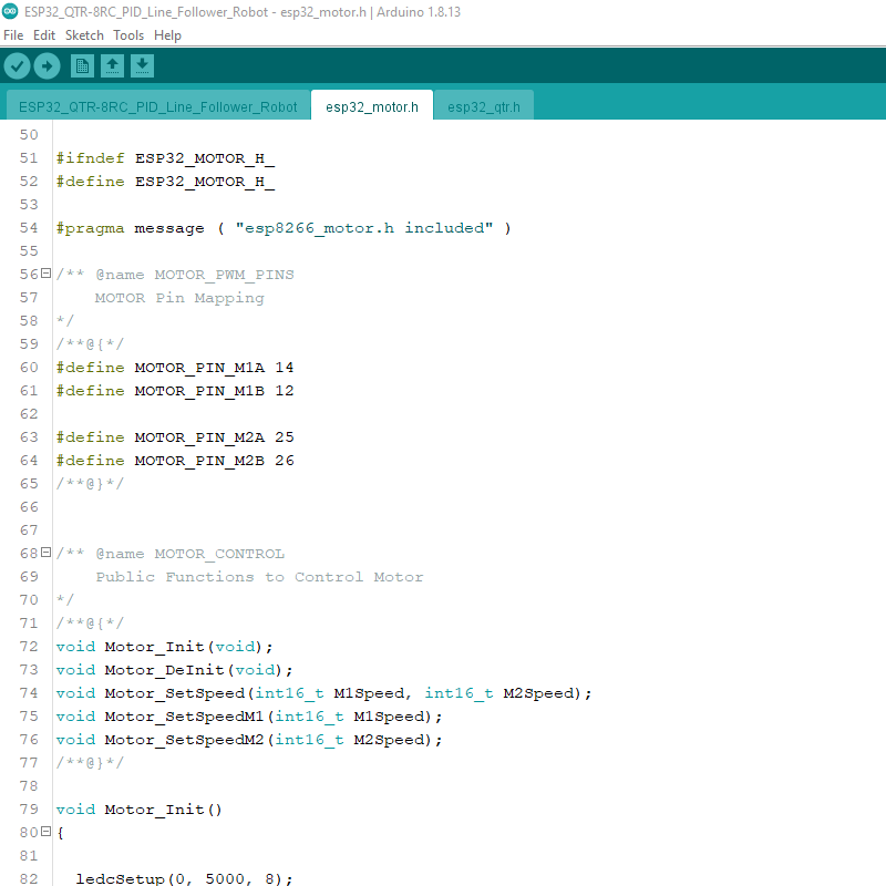
The firmware project has three library files esp32_qtr.h , esp32_motor.h and one main.c file. The library file code is written in C. The library files are all well documented. The APIs exposed can be used in Arduino IDE. The programming language used in C.
/** @name QTR_CONTROL
    Public Functions to Control QTR Sensor
*/
void QTR_Init(uint8_t *SensorPin, uint8_t EmitterPin);
void QTR_DeInit();
void QTR_Calibrate(uint16_t *CalibratedMinimum, uint16_t *CalibratedMaximum, uint8_t ReadMode);
void QTR_CalibrateSensor(uint8_t ReadMode);
void QTR_ResetCalibration();
void QTR_ReadSensor(uint16_t *SensorValues, uint8_t ReadMode);
void QTR_ReadRaw(uint16_t *SensorValues);
void QTR_ReadCalibrated(uint16_t *SensorValues, uint8_t ReadMode);
uint16_t QTR_ReadLine(uint16_t *SensorValues, uint8_t ReadMode);
inline void QTR_EmitterOn();
inline void QTR_EmitterOff();
/**@}*/
/** @name MOTOR_CONTROL
Public Functions to Control Motor
*/
/**@{*/
void Motor_Init(void);
void Motor_DeInit(void);
void Motor_SetSpeed(int16_t M1Speed, int16_t M2Speed);
void Motor_SetSpeedM1(int16_t M1Speed);
void Motor_SetSpeedM2(int16_t M2Speed);
/**@}*/License
All Rights Reserved

Copyright (c) 2022 Arnab Kumar Das

THE SOFTWARE IS PROVIDED "AS IS", WITHOUT WARRANTY OF ANY KIND, EXPRESS OR
IMPLIED, INCLUDING BUT NOT LIMITED TO THE WARRANTIES OF MERCHANTABILITY,
FITNESS FOR A PARTICULAR PURPOSE AND NONINFRINGEMENT. IN NO EVENT SHALL THE
AUTHORS OR COPYRIGHT HOLDERS BE LIABLE FOR ANY CLAIM, DAMAGES OR OTHER
LIABILITY, WHETHER IN AN ACTION OF CONTRACT, TORT OR OTHERWISE, ARISING FROM,
OUT OF OR IN CONNECTION WITH THE SOFTWARE OR THE USE OR OTHER DEALINGS IN THE
SOFTWARE.
PID Line Follower Robot Code Walkthrough
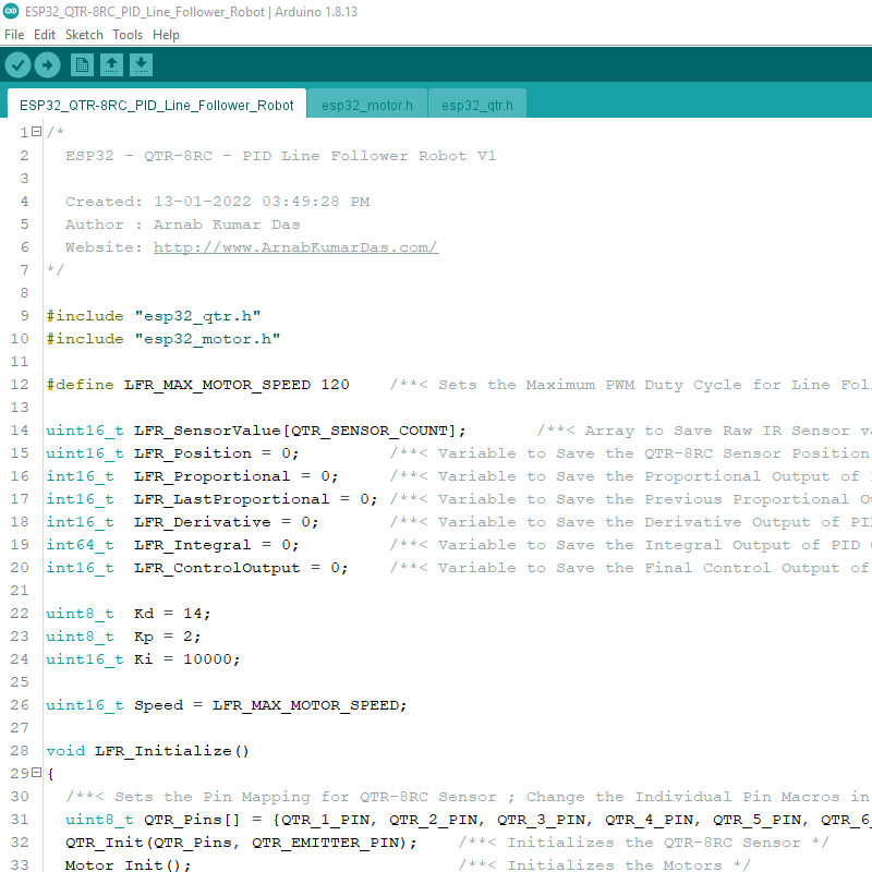
The first few lines of code declare all the variables needed for the PID algorithm.
uint16_t LFR_SensorValue[QTR_SENSOR_COUNT];       /**< Array to Save Raw IR Sensor values of QTR-8RC */
uint16_t LFR_Position = 0;         /**< Variable to Save the QTR-8RC Sensor Position */
int16_t  LFR_Proportional = 0;     /**< Variable to Save the Proportional Output of PID Control Algorithm */
int16_t  LFR_LastProportional = 0; /**< Variable to Save the Previous Proportional Output of PID Control Algorithm */
int16_t  LFR_Derivative = 0;       /**< Variable to Save the Derivative Output of PID Control Algorithm */
int64_t  LFR_Integral = 0;         /**< Variable to Save the Integral Output of PID Control Algorithm */
int16_t  LFR_ControlOutput = 0;    /**< Variable to Save the Final Control Output of PID Control Algorithm */

uint8_t  Kd = 14;
uint8_t  Kp = 2;
uint16_t Ki = 10000;

uint16_t Speed = LFR_MAX_MOTOR_SPEED;
The function “LFR_Initialize()” initializes all used peripherals of the ESP32. The QTR_X_PIN macros are defined in the esp32_qtr.h file.
void LFR_Initialize()
{
  uint8_t QTR_Pins[] = {QTR_1_PIN, QTR_2_PIN, QTR_3_PIN, QTR_4_PIN, QTR_5_PIN, QTR_6_PIN, QTR_7_PIN, QTR_8_PIN};
  QTR_Init(QTR_Pins, QTR_EMITTER_PIN);    /**< Initializes the QTR-8RC Sensor */
  Motor_Init();                           /**< Initializes the Motors */
  delay(2000);                            /**< Pause ; Useful to Align the Robot Manually if Outside the Line */
}
The function “LFR_Calibrate()” calibrates the QTR-8RC line sensor. The robot rotates in the same place and calibrates the sensor with all possible sensor values sampled during this time.
void LFR_Calibrate()
{
  Motor_SetSpeed(90, -90);         /**< Rotates the Robot 90, -90 300RPM */
  for (uint8_t i = 0; i < 40; i++) /**< Calibrate the QTR-8RC Sensor */
  {
    QTR_CalibrateSensor(QTR_EMITTERS_ON);
    delay(20);
  }
  Motor_SetSpeed(0, 0);            /**< Stops the Robot */
  delay(500);
  Motor_SetSpeed(-90, 90);         /**< Rotates the Robot */
  for (uint8_t i = 0; i < 80; i++) /**< Calibrate the QTR-8RC Sensor */
  {
    QTR_CalibrateSensor(QTR_EMITTERS_ON);
    delay(20);
  }
  Motor_SetSpeed(0, 0);            /**< Stops the Robot */
  delay(500);
  Motor_SetSpeed(90, -90);         /**< Rotates the Robot */
  for (uint8_t i = 0; i < 40; i++) /**< Calibrate the QTR-8RC Sensor */
  {
    QTR_CalibrateSensor(QTR_EMITTERS_ON);
    delay(20);
  }
  Motor_SetSpeed(0, 0);         /**< Stops the Robot */
  delay(2000);                  /**< Pause ; Useful to Realign the Robot Manually if Outside the Line */
}
The infinite while loop below is responsible for the PID algorithm. The current gains Kp=1/2, Ki=1/10000, and Kd=14 should make the Line Follower Robot work out of the box if a similar construction is done. It is good to note that PID coefficients depend heavily on physical parameters like the size of the robot, weight, proportions, battery voltage, friction, etc. It is always advised to tune your robot after any hardware change.
void loop()
{
  LFR_Position = QTR_ReadLine(LFR_SensorValue, QTR_EMITTERS_ON);    /**< Reads the QTR-8RC Line Sensor to Get the Line Position */

  LFR_Proportional = LFR_Position - QTR_LINE_MID_VALUE;             /**< Computes the Proportional Output of PID Control Algorithm */
  LFR_Derivative = LFR_Proportional - LFR_LastProportional;         /**< Computes the Derivative Output of PID Control Algorithm */
  LFR_Integral += LFR_Proportional;                                 /**< Computes the Integral Output of PID Control Algorithm */
  LFR_LastProportional = LFR_Proportional;                          /**< Saves the Old Proportional Output of PID Control Algorithm */

  LFR_ControlOutput = LFR_Proportional / Kp + LFR_Integral / Ki + LFR_Derivative * Kd; /**< Computes the Final Control Output of PID Control Algorithm 300RPM*/

  if (LFR_ControlOutput > Speed)
  {
    LFR_ControlOutput = Speed;    /**< Keeps The Motor Speed in Limit */
  }
  if (LFR_ControlOutput < -Speed)
  {
    LFR_ControlOutput = -Speed;    /**< Keeps The Motor Speed in Limit */
  }

  if (LFR_ControlOutput < 0)
  {
    Motor_SetSpeed(Speed + LFR_ControlOutput, Speed);    /**< Drives the Motor According to the Control Output */
  }
  else
  {
    Motor_SetSpeed(Speed, Speed - LFR_ControlOutput);    /**< Drives the Motor According to the Control Output */
  }
}
The speed of the line follower robot is controlled by the macro LFR_MAX_MOTOR_SPEED . It is advised to recalibrate the robot at a higher speed for optimum performance.
#define LFR_MAX_MOTOR_SPEED 125 /**< Sets the Maximum PWM Duty Cycle for Line Follower Robot 0=0% 255=100% */Programming The ESP32 Line Follower Robot
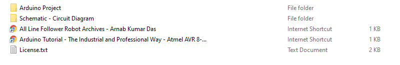
The project folder has all the required files. If you use Arduino IDE then open the Arduino project folder and flash the ESP32 from Arduino IDE.

5 Comments
Kenny · July 5, 2022 at 7:56 pm
Hi, thank you for this project. I’m a little bit confused about the QTR connection to the ESP32 and motor driver. Could you expantiate?
Crazy Engineer · July 6, 2022 at 10:10 pm
How can I help You?
Kenny · July 18, 2022 at 6:24 pm
I’m trying to use a breadboard to do the same connection but it seems I’m not getting the connection right. Could u share with me the circuit diagram?
JARI · March 29, 2024 at 3:47 pm
hey kenny, u ever got the circuit diagram? or u figured out yourself?
plz i also need help with the circuit…
emir · April 19, 2024 at 9:58 pm
How can i get access to these libraries