Introduction
Smart dustbins are becoming increasingly popular as a way to help manage waste. These bins are equipped with sensors that can detect when they are full and need to be emptied. This information is then transmitted to a central location, where it can be monitored and managed. This helps to ensure that bins are emptied on a regular basis, and that waste is properly managed.
This project has ESP32 and SIM800L for Wi-Fi, BLE and Cellular Communication. It is capable of measuring dustbin contents and updating cloud servers for efficient emptying of dustbins. The typical use case is public places, airports and railway stations.
The whole project is designed, manufactured and assembled in-house.
What You Will Learn
- How to make an ESP32 battery powered IoT device?
- How ultrasonic sensor works?
- How to connect to internet via GSM?
- How to handle multiple communication protocol in single system?
Prerequisite
- Knowledge of C Programming
- Background knowledge of ESP32
- Background knowledge of GPIO
- Background knowledge of TIMER
- Background knowledge of UART
- Basic knowledge of Electronics
Hardware Bill of Materials
- ESP32 Node MCU – 1pc
- Ultrasonic Sensor HC-SR04 – 3pc
- GSM Module SIM800L – 1pc
- Li-Ion Battery – 2pc
- Li-Ion Battery Holder – 2pc
- Misc Passive Components
Software Bill of Materials
Hardware Description
ESP32 Node MCU Board
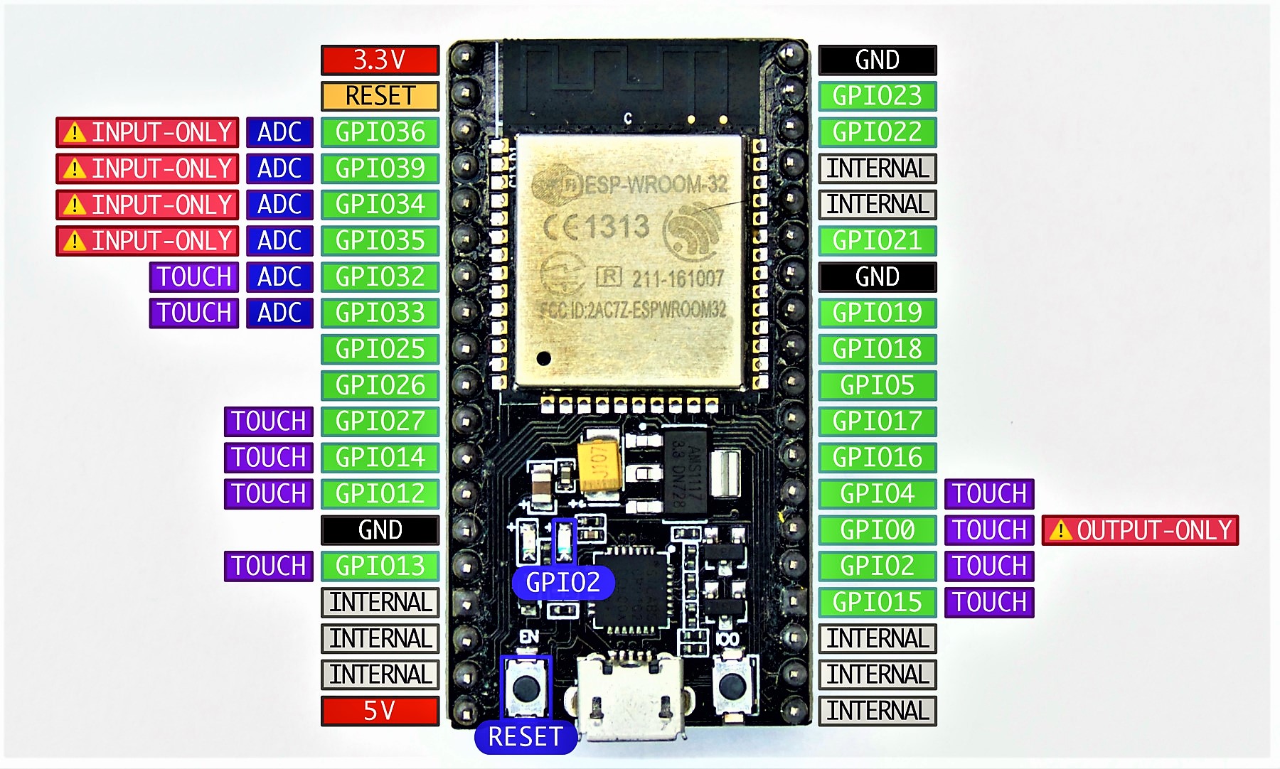
Specification of NodeMCU ESP32
| Microcontroller | ESP32 ( |
| Operating Voltage | 3.3V |
| Flash Memory | 4MB |
| SRAM | 512KB |
| Clock Speed | 240MHz |
| Analog IN Pins | 5 |
| Digital I/O Pins | 24 (Usable) |
| PCB Size | 25mm x 50mm |
Ultrasonic Sensor HC-SR04

This sensor provides a 2cm to 400cm range of non-contact measurement capability with a ranging accuracy that reaches up to 3mm. The HC-SR04 module consists of an ultrasonic transmitter, receiver and control circuit. Only 4 pins are needed to operate the device; power supply voltage (VCC), trigger signal (TRIG), echo signal (ECHO) and ground (GND).
GSM Module SIM800L
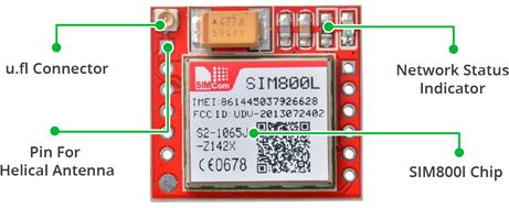
The SIM800L GSM/GPRS module is a miniature GSM modem that can be integrated into many IoT projects. With this module, you can do almost everything that an ordinary mobile phone can do, such as send text messages, make calls, connect to the Internet via GPRS, and much more.
Circuit Design
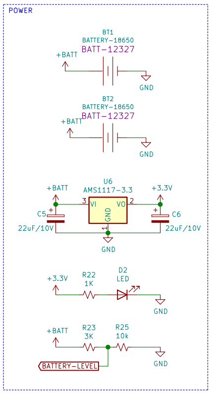
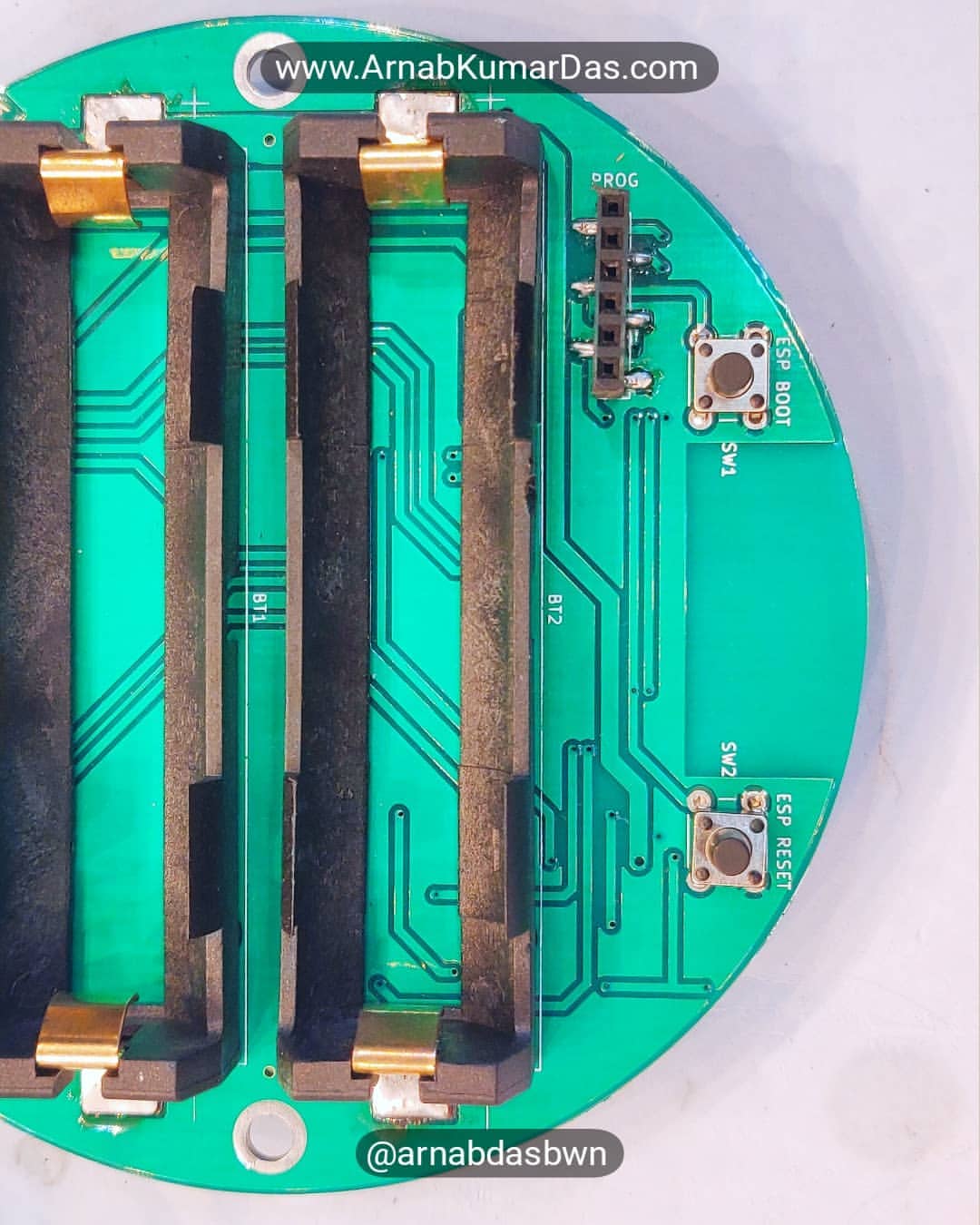
Power System Design
The Smart Dustbin has two types of components in it, one working at 3.3V and another at 4.2V. The microcontroller runs at 3.3V. Whereas the ultrasonic sensors and GSM module work at 4.2V. AMS1117 converter provides a 3.3V constant voltage power supply from a 1S 2P Li-Ion battery pack. The battery pack provides 4.2V when full charge and 3.7V when fully discharged. The SIM800L module and ultrasonic sensor get directly connected to the Li-Ion battery pack.
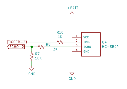
Ultrasonic Sensor Design
The ESP32 Smart Dustbin uses three HC-SR04 ultrasonic sensors for measuring the amount of waste in the dustbin. The ultrasonic sensor operates at 4.2V and gets connected to the battery output. The ultrasonic sensor has one sensor output and one trigger input. The sensor outputs an ECHO Pin and goes to the microcontroller’s GPIO via a voltage divider as ESP32 accepts a 3.3V logic level. The TRIGGER is an input pin for the ultrasonic and it controls the start of the ultrasonic measurement.
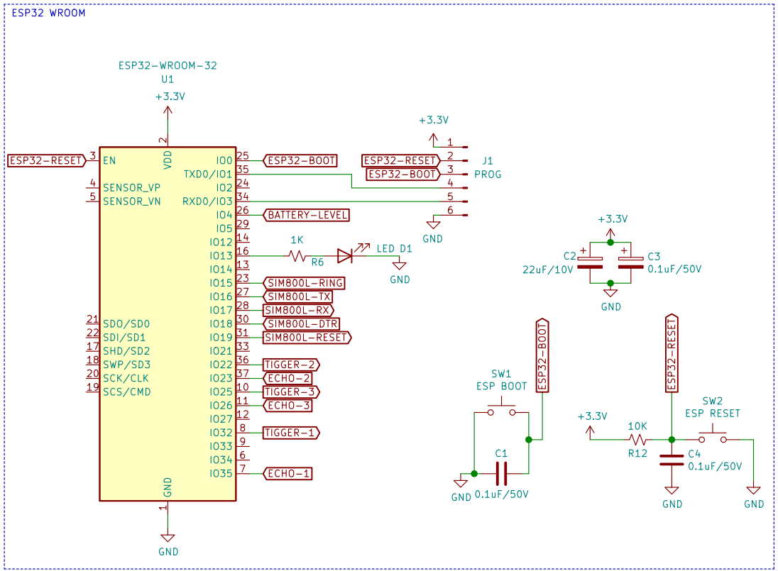
Microcontroller Design
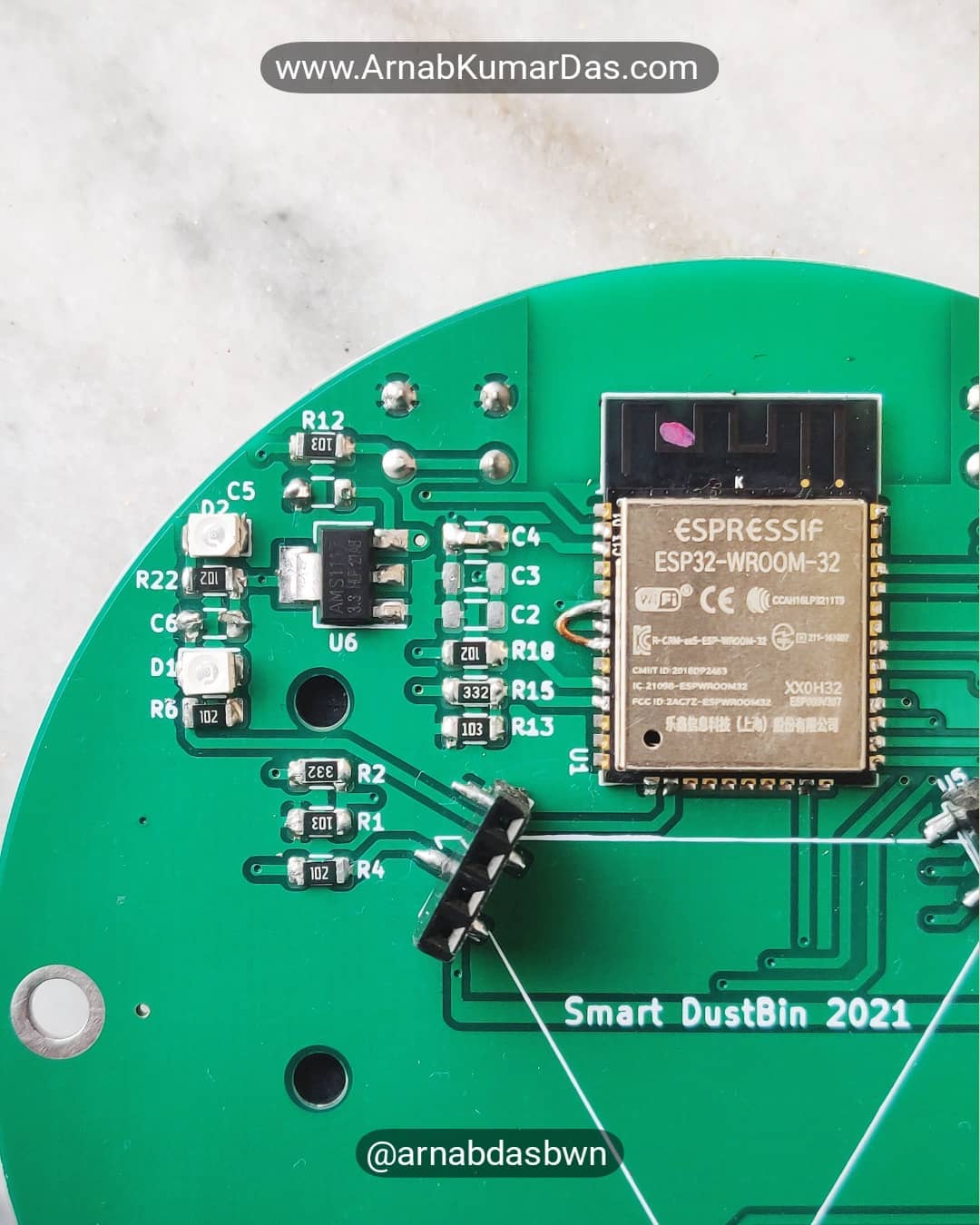
The Smart IoT Dutbin uses an ESP32 NodeMCU board as the control unit. NodeMCU runs at 3.3V and is connected to the linear converter’s 3.3V output.
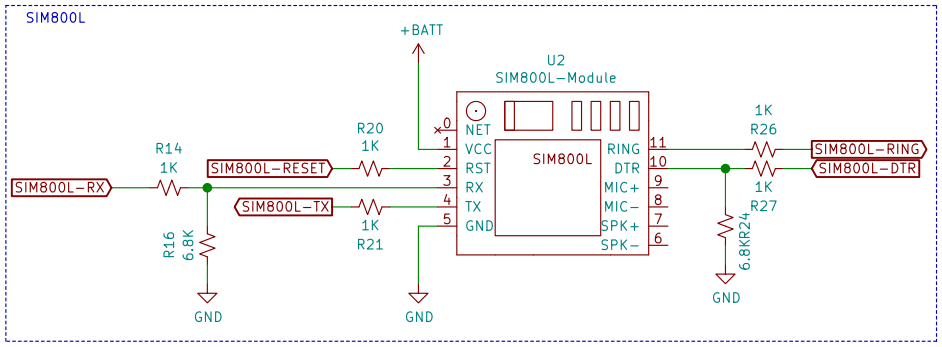
GSM Module SIM800L Design
SIM800L runs on battery power and gets directly connected to the 4.2V line. The output pins of SIM800L get connected to ESP32 via a voltage divider to keep the levels at 3.3V.
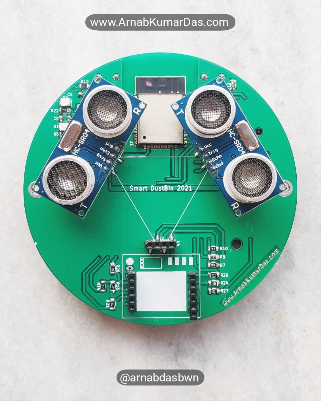
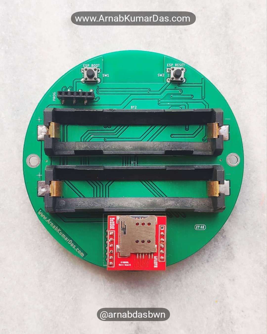
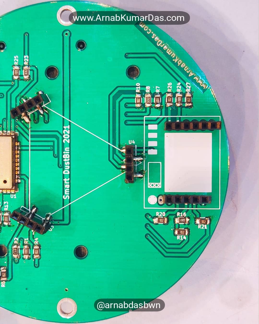
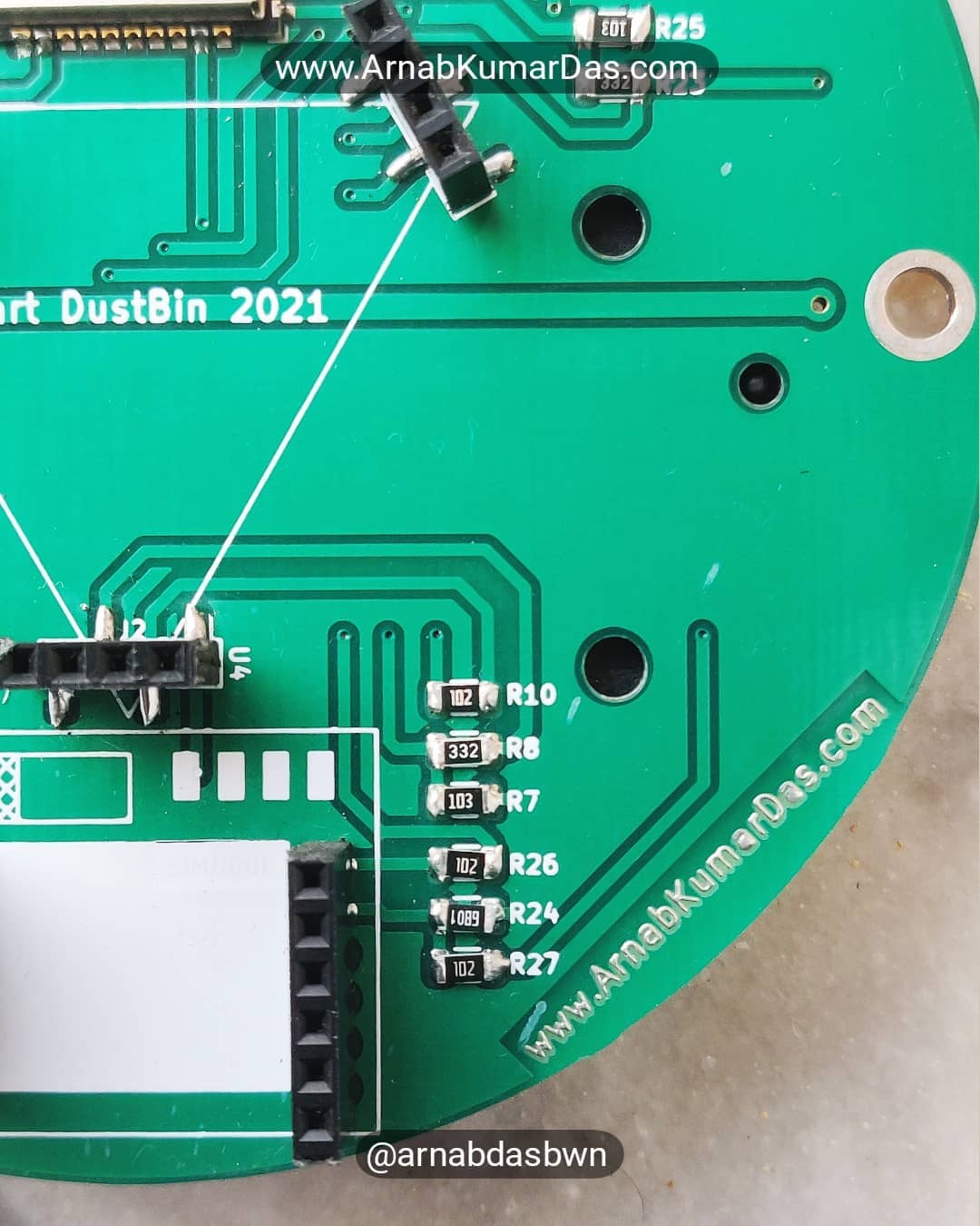
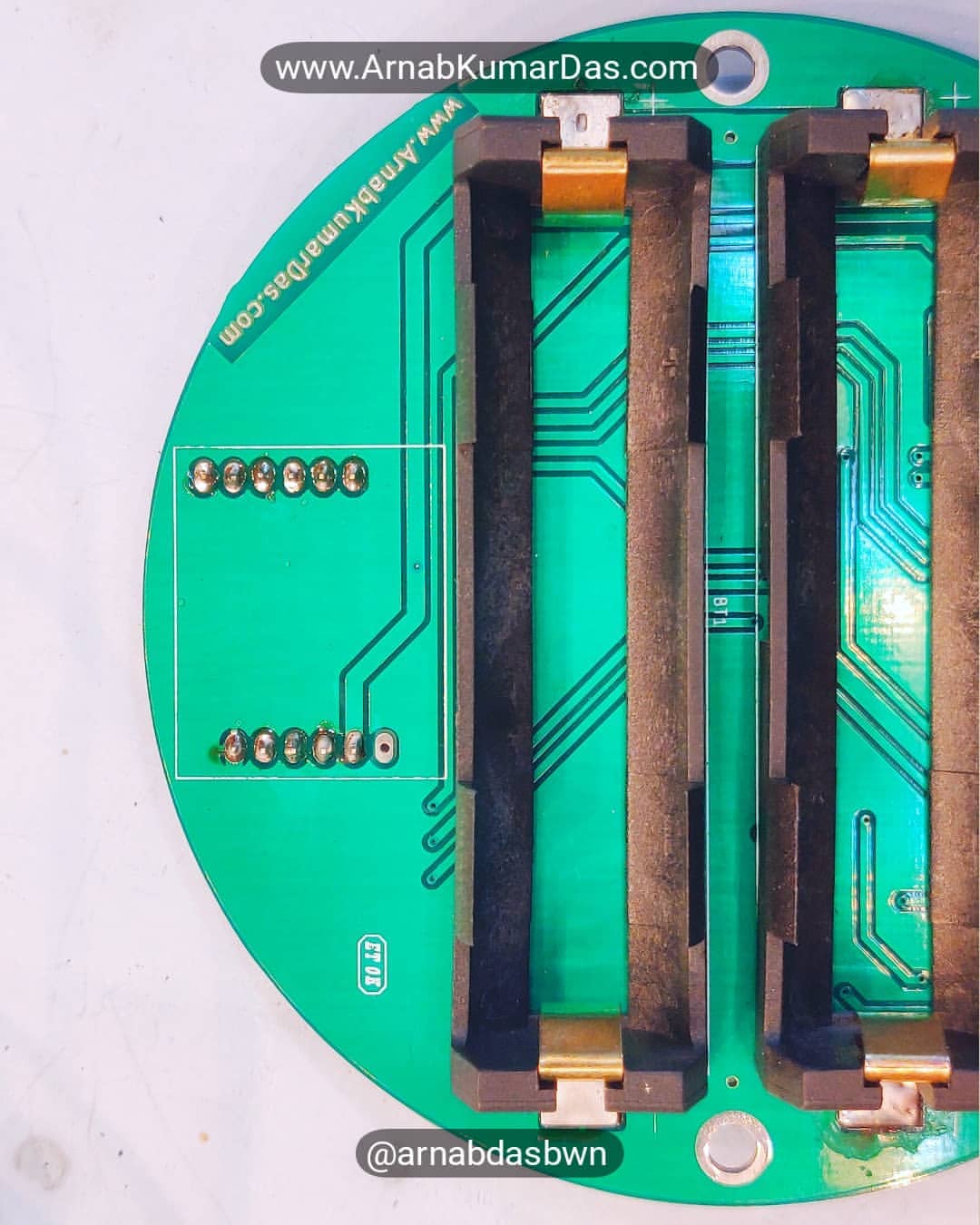
PCB Render

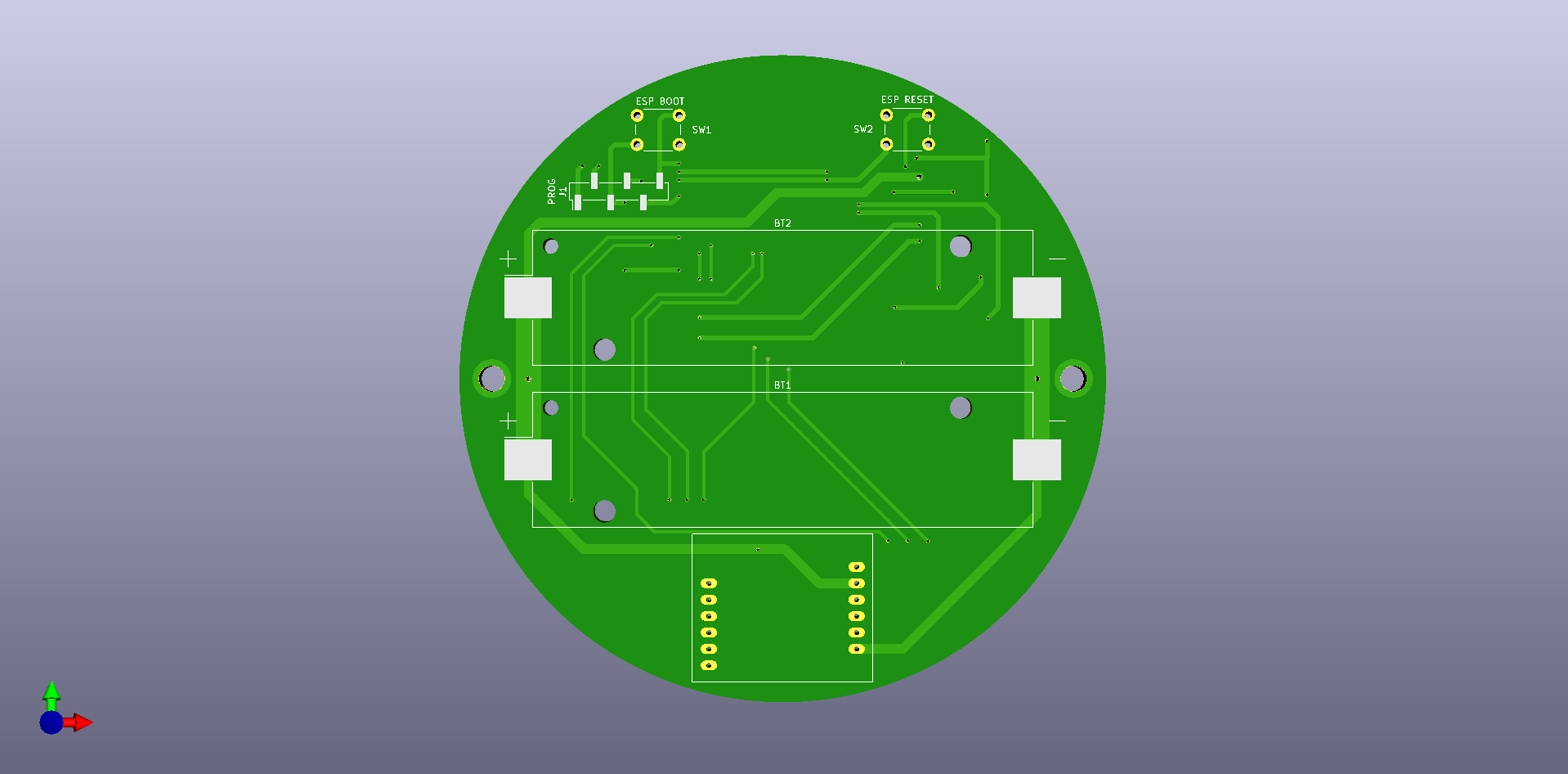
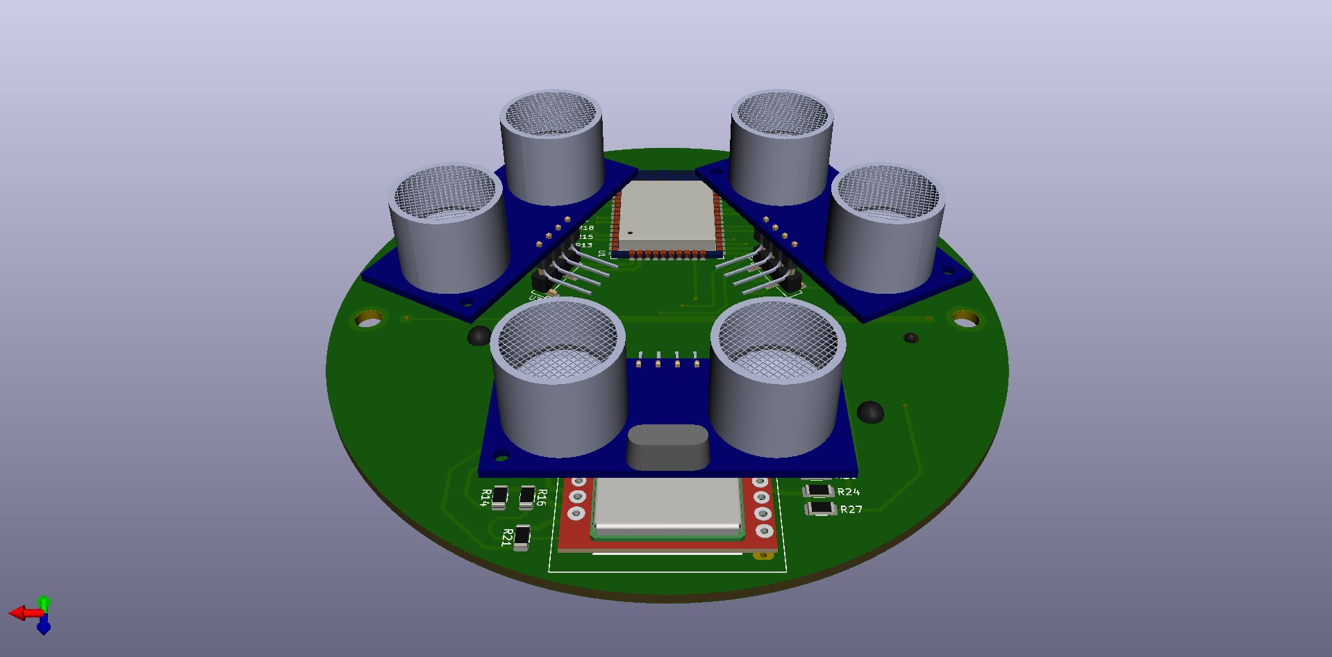
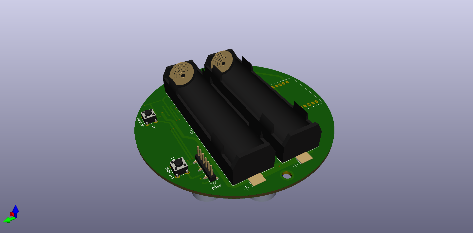
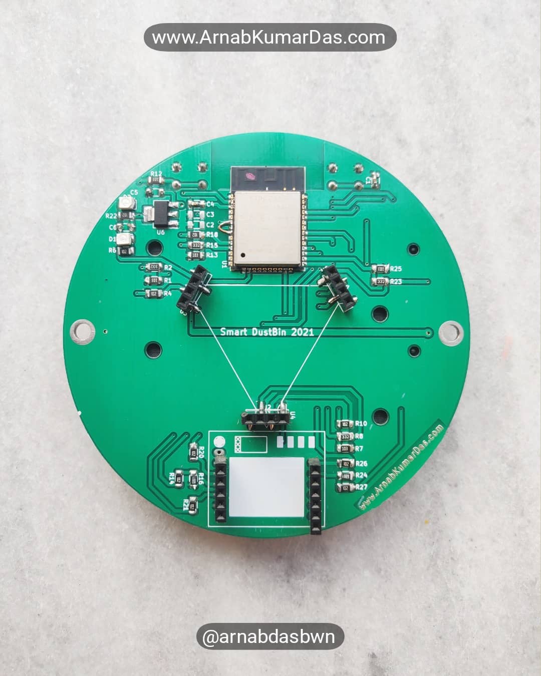
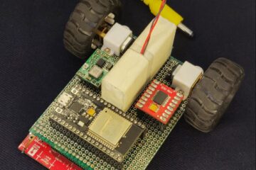
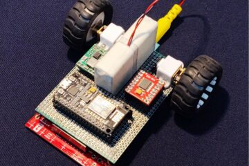
Making the Smart Dustbin
Code / Software Description
const int trigPin1 = 13;
const int echoPin1 = 12;

const int trigPin2 = 22;
const int echoPin2 = 23;

const int trigPin3 = 25;
const int echoPin3 = 26;


//define sound speed in cm/uS
#define SOUND_SPEED 0.034
#define CM_TO_INCH 0.393701

long duration;
float distanceCm;
float distanceInch;

void setup() {
  Serial.begin(115200); // Starts the serial communication
  pinMode(trigPin1, OUTPUT); // Sets the trigPin as an Output
  pinMode(echoPin1, INPUT); // Sets the echoPin as an Input
  pinMode(trigPin2, OUTPUT); // Sets the trigPin as an Output
  pinMode(echoPin2, INPUT); // Sets the echoPin as an Input
  pinMode(trigPin3, OUTPUT); // Sets the trigPin as an Output
  pinMode(echoPin3, INPUT); // Sets the echoPin as an Input
}

void loop() {
  // Clears the trigPin
  digitalWrite(trigPin1, LOW);
  delayMicroseconds(2);
  // Sets the trigPin on HIGH state for 10 micro seconds
  digitalWrite(trigPin1, HIGH);
  delayMicroseconds(10);
  digitalWrite(trigPin1, LOW);

  // Reads the echoPin, returns the sound wave travel time in microseconds
  duration = pulseIn(echoPin1, HIGH);

  // Calculate the distance
  distanceCm = duration * SOUND_SPEED / 2;

  // Convert to inches
  distanceInch = distanceCm * CM_TO_INCH;

  // Prints the distance in the Serial Monitor
  Serial.print("Distance (cm): ");
  Serial.println(distanceCm);
  Serial.print("Distance (inch): ");
  Serial.println(distanceInch);

  delay(1000);

  // Clears the trigPin
  digitalWrite(trigPin2, LOW);
  delayMicroseconds(2);
  // Sets the trigPin on HIGH state for 10 micro seconds
  digitalWrite(trigPin2, HIGH);
  delayMicroseconds(10);
  digitalWrite(trigPin2, LOW);

  // Reads the echoPin, returns the sound wave travel time in microseconds
  duration = pulseIn(echoPin2, HIGH);

  // Calculate the distance
  distanceCm = duration * SOUND_SPEED / 2;

  // Convert to inches
  distanceInch = distanceCm * CM_TO_INCH;

  // Prints the distance in the Serial Monitor
  Serial.print("Distance (cm): ");
  Serial.println(distanceCm);
  Serial.print("Distance (inch): ");
  Serial.println(distanceInch);

  delay(1000);

  // Clears the trigPin
  digitalWrite(trigPin3, LOW);
  delayMicroseconds(2);
  // Sets the trigPin on HIGH state for 10 micro seconds
  digitalWrite(trigPin3, HIGH);
  delayMicroseconds(10);
  digitalWrite(trigPin3, LOW);

  // Reads the echoPin, returns the sound wave travel time in microseconds
  duration = pulseIn(echoPin3, HIGH);

  // Calculate the distance
  distanceCm = duration * SOUND_SPEED / 2;

  // Convert to inches
  distanceInch = distanceCm * CM_TO_INCH;

  // Prints the distance in the Serial Monitor
  Serial.print("Distance (cm): ");
  Serial.println(distanceCm);
  Serial.print("Distance (inch): ");
  Serial.println(distanceInch);

  delay(1000);
}
// SIM card PIN (leave empty, if not defined)
const char simPIN[] = "";
#define SMS_TARGET "+351XXXXXXXXX"
// Configure TinyGSM library
#define TINY_GSM_MODEM_SIM800 // Modem is SIM800
#define TINY_GSM_RX_BUFFER 1024 // Set RX buffer to 1Kb
#include <TinyGsmClient.h>
// TTGO T-Call pins
#define MODEM_RST 19
#define MODEM_TX 17
#define MODEM_RX 16
// Set serial for debug console (to Serial Monitor, default speed 115200)
#define SerialMon Serial
// Set serial for AT commands (to SIM800 module)
#define SerialAT Serial1
// Define the serial console for debug prints, if needed
#define DUMP_AT_COMMANDS
#ifdef DUMP_AT_COMMANDS
#include <StreamDebugger.h>
StreamDebugger debugger(SerialAT, SerialMon);
TinyGsm modem(debugger);
#else
TinyGsm modem(SerialAT);
#endif
void setup() {
// Set console baud rate
SerialMon.begin(115200);
// Set modem reset, enable, power pins
pinMode(MODEM_RST, OUTPUT);
digitalWrite(MODEM_RST, HIGH);
// Set GSM module baud rate and UART pins
SerialAT.begin(115200, SERIAL_8N1, MODEM_RX, MODEM_TX);
delay(3000);
// Restart SIM800 module, it takes quite some time
// To skip it, call init() instead of restart()
SerialMon.println("Initializing modem...");
modem.restart();
// use modem.init() if you don't need the complete restart
// To send an SMS, call modem.sendSMS(SMS_TARGET, smsMessage)
String smsMessage = "Hello from ESP32!";
if (modem.sendSMS(SMS_TARGET, smsMessage)) {
SerialMon.println(smsMessage);
}
else {
SerialMon.println("SMS failed to send");
}
}
void loop() {
delay(1);
}License
All Rights Reserved

Copyright (c) 2022 Arnab Kumar Das

THE SOFTWARE IS PROVIDED "AS IS", WITHOUT WARRANTY OF ANY KIND, EXPRESS OR
IMPLIED, INCLUDING BUT NOT LIMITED TO THE WARRANTIES OF MERCHANTABILITY,
FITNESS FOR A PARTICULAR PURPOSE AND NONINFRINGEMENT. IN NO EVENT SHALL THE
AUTHORS OR COPYRIGHT HOLDERS BE LIABLE FOR ANY CLAIM, DAMAGES OR OTHER
LIABILITY, WHETHER IN AN ACTION OF CONTRACT, TORT OR OTHERWISE, ARISING FROM,
OUT OF OR IN CONNECTION WITH THE SOFTWARE OR THE USE OR OTHER DEALINGS IN THE
SOFTWARE.
0 Comments