INTRODUCTION to Three Phase Rectifier Hack For Using a Brushless (BLDC) Motor ESC as a Brushed Motor ESC
This article talks about three phase rectifier and shows a hack how to use three phase rectifier to use BLDC Motor’s ESC as Brushed DC Motor’s ESC. So if you are out of Brushed Motor ESC you can now always convert them to Brushless Motor ESC.
BRUSHED MOTOR
A brushed DC motor is an internally commutated electric motor designed to be run from a direct current power source. Brushed DC motors can be varied in speed by changing the operating voltage or the strength of the magnetic field. Depending on the connections of the field to the power supply, the speed and torque characteristics of a brushed motor can be altered to provide steady speed or speed inversely proportional to the mechanical load. Since the brushes wear down and require replacement, brushless DC motors using power electronic devices have displaced brushed motors from many applications.

Permanent Magnet DC Motor Found in Toy
DC motor rotation


 Generally, the rotational speed of a DC motor is proportional to the EMF in its coil (= the voltage applied to it minus voltage lost on its resistance), and the torque is proportional to the current. Speed control can be achieved by variable battery tappings, variable supply voltage, resistors or electronic controls. The direction of a wound field DC motor can be changed by reversing either the field or armature connections but not both. This is commonly done with a special set of contactors (direction contactors). The effective voltage can be varied by inserting a series resistor or by an electronically controlled switching device made of thyristors, transistors, or, formerly, mercury arc rectifiers.
BRUSHLESS MOTOR
Brushless DC electric motor (BLDC motors, BL motors) also known as electronically commutated motors (ECMs, EC motors), or synchronous DC motors, are synchronous motors powered by DC electricity via an inverter or switching power supply which produces an AC electric current to drive each phase of the motor via a closed loop controller. The controller provides pulses of current to the motor windings that control the speed and torque of the motor.
The construction of a brushless motor system is typically similar to a permanent magnet synchronous motor (PMSM), but can also be a switched reluctance motor, or an induction (asynchronous) motor.
The advantages of a brushless motor over brushed motors are high power to weight ratio, high speed, and electronic control. Brushless motors find applications in such places as computer peripherals (disk drives, printers), hand-held power tools, and vehicles ranging from model aircraft to automobiles.
-

- Inside BLDC Motor
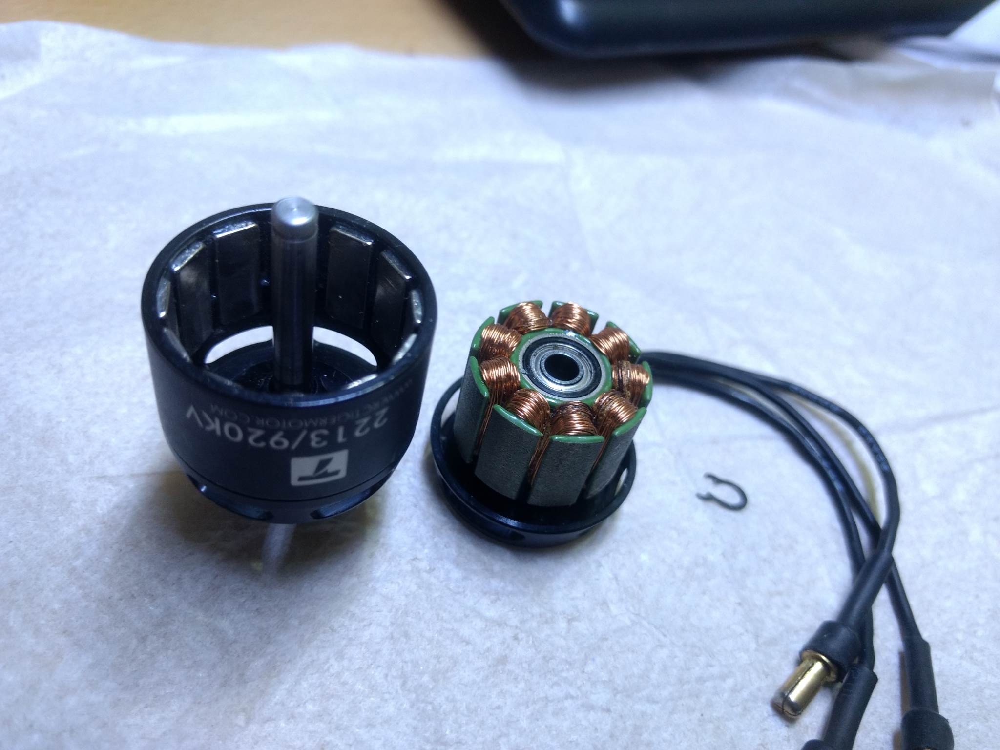
-
- Inside BLDC Motor

MOTOR ESC
An electronic speed control or ESC is an electronic circuit that controls and regulates the speed of an electric motor. It may also provide reversing of the motor and dynamic braking. Miniature electronic speed controls are used in electrically powered radio controlled models. Full-size electric vehicles also have systems to control the speed of their drive motors.
An electronic speed control follows a speed reference signal (derived from a throttle lever, joystick, or other manual input) and varies the switching rate of a network of field effect transistors (FETs). By adjusting the duty cycle or switching frequency of the transistors, the speed of the motor is changed. The rapid switching of the transistors is what causes the motor itself to emit its characteristic high-pitched whine, especially noticeable at lower speeds.
Different types of speed controls are required for brushed DC motors and brushless DC motors. A brushed motor can have its speed controlled by varying the voltage on its armature. (Industrially, motors with electromagnet field windings instead of permanent magnets can also have their speed controlled by adjusting the strength of the motor field current.) A brushless motor requires a different operating principle. The speed of the motor is varied by adjusting the timing of pulses of current delivered to the several windings of the motor.

A generic ESC module rated at 35 amperes with an integrated BEC
Brushless ESC systems basically create three-phase AC power, as in a variable frequency drive, to run brushless motors. Brushless motors are popular with radio controlled aeroplane hobbyists because of their efficiency, power, longevity and lightweight in comparison to traditional brushed motors. Brushless AC motor controllers are much more complicated than brushed motor controllers.
The correct phase varies with the motor rotation, which is to be taken into account by the ESC: Usually, back EMF from the motor is used to detect this rotation, but variations exist that use magnetic (Hall effect) or optical detectors. Computer-programmable speed controls generally have user-specified options which allow setting low voltage cut-off limits, timing, acceleration, braking and direction of rotation. Reversing the motor’s direction may also be accomplished by switching any two of the three leads from the ESC to the motor.
ESCs are normally rated according to maximum current, for example, 25 amperes or 25 A. Generally the higher the rating, the larger and heavier the ESC tends to be which is a factor when calculating mass and balance in aeroplanes. Many modern ESCs support nickel metal hydride, lithium ion polymer and lithium iron phosphate batteries with a range of input and cut-off voltages. The type of battery and number of cells connected is an important consideration when choosing a battery eliminator circuit (BEC), whether built into the controller or as a stand-alone unit. A higher number of cells connected will result in a reduced power rating and therefore a lower number of servos supported by an integrated BEC, if it uses a linear voltage regulator. A well designed BEC using a switching regulator should not have a similar limitation.
Electronic Speed Controllers (ESC) are an essential component of modern quadcopters (and all multirotors) that offer high power, high frequency, high-resolution 3-phase AC power to the motors in an extremely compact miniature package. These crafts depend entirely on the variable speed of the motors driving the propellers. This wide variation and fine RPM control in motor/prop speed give all of the control necessary for a quadcopter (and all multirotors) to fly. The ESC generally accepts a nominal 50 Hz PWM servo input signal whose pulse width varies from 1 ms to 2 ms. When supplied with a 1 ms width pulse at 50 Hz, the ESC responds by turning off the motor attached to its output. A 1.5 ms pulse-width input signal drives the motor at approximately half-speed. When presented with 2.0 ms input signal, the motor runs at full speed.
Quadcopter ESCs usually can use a faster update rate compared to the standard 50 Hz signal used in most other RC applications. A variety of ESC protocols beyond PWM are utilized for modern-day multirotors, including, Oneshot42, Oneshot125, Multishot, and DShot. DShot is a digital protocol that offers certain advantages over classical analogue control, such as higher resolution, CRC checksums, and a lack of oscillator drift (removing the need for calibration). Modern-day ESCs protocols can communicate at speeds of 37.5KHz or greater, with DSHOT2400 frame only taking 6.5μs.
CONVERTING A BRUSHLESS ESC TO BRUSHED ESC
So in simple terms, a Brushless ESC outputs a 3 phase AC and thus can be rectified to DC. Most common type of rectifiers is a single phase rectifier.
A rectifier is an electrical device that converts alternating current (AC), which periodically reverses direction, to direct current (DC), which flows in only one direction. The process is known as rectification, since it “straightens” the direction of the current. Physically, rectifiers take a number of forms, including vacuum tube diodes, mercury-arc valves, stacks of copper and selenium oxide plates, semiconductor diodes, silicon-controlled rectifiers and other silicon-based semiconductor switches. Historically, even synchronous electromechanical switches and motors have been used. Early radio receivers, called crystal radios, used a “cat’s whisker” of fine wire pressing on a crystal of galena (lead sulfide) to serve as a point-contact rectifier or “crystal detector”.
With AC input, the output of a diode bridge (called a full-wave rectifier for this purpose; there is also half-wave rectification, which does not use a diode bridge) is polarized pulsating non-sinusoidal voltage of the same amplitude but twice the frequency of the input. It may be considered as DC voltage upon which is superimposed a very large ripple voltage. This kind of electric power is not very usable, because ripple is dissipated as waste heat in DC circuit components and may cause noise or distortion during circuit operation. So nearly all rectifiers are followed by a series of bandpass or bandstop filters and/or a voltage regulator to convert most or all of the ripple voltage into a smoother and possibly higher DC output. A filter may be as simple as a single sufficiently large capacitor or choke, but most power-supply filters have multiple alternating series and shunt components. When the ripple voltage rises, reactive power is stored in the filter components, reducing the voltage; when the ripple voltage falls, reactive power is discharged from the filter components, raising the voltage. The final stage of rectification may consist of a zener diode-based voltage regulator, which almost completely eliminates any residual ripple.
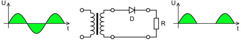
Half-Wave Single Phase Rectifier
Graetz bridge rectifier: a full-wave rectifier using four diodes
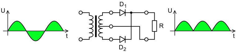
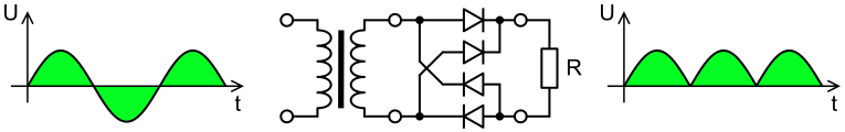
Full-wave rectifier using a centre tap transformer and 2 diodes
Single-phase rectifiers are commonly used for power supplies for domestic equipment. However, for most industrial and high-power applications, three phase rectifier circuits are the norm. As with single-phase rectifiers, three phase rectifier can take the form of a half-wave circuit, a full-wave circuit using a centre-tapped transformer, or a full-wave bridge circuit.
Thyristors are commonly used in place of diodes to create a circuit that can regulate the output voltage. Many devices that provide direct current actually generate three phase AC. For example, an automobile alternator contains six diodes, which function as a full-wave rectifier for battery charging. Three Phase Rectifier also need filtering at the output to smooth out the ripples.
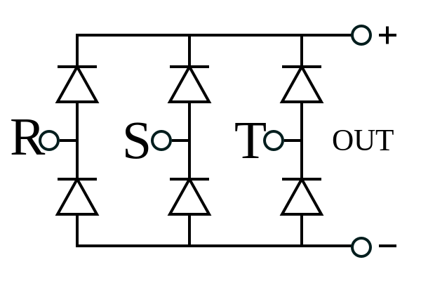
Three Phase Bridge Rectifier
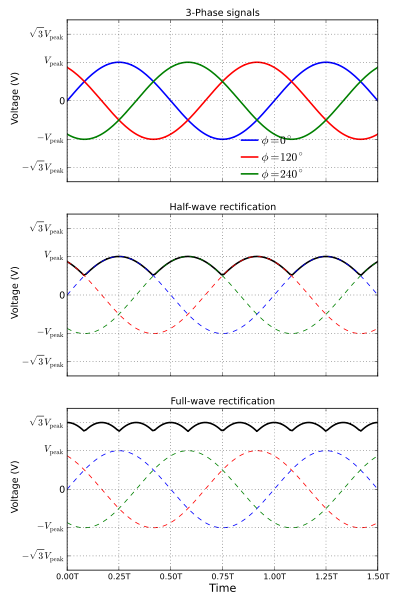
3-phase AC input waveform (top), half-wave rectified waveform (center), and full-wave rectified waveform (bottom)
In the below-attached picture, you can see I have attached 6 diodes according to the circuit diagram above. For silicon diodes, the built-in potential is approximately 0.7 V (0.3 V for germanium and 0.2 V for Schottky). Thus, if an external voltage greater than and opposite to the built-in voltage is applied, a current will flow and the diode is said to be “turned on” as it has been given an external forward bias. The diode is commonly said to have a forward “threshold” voltage, above which it conducts and below which conduction stops.
So 0.7V forward voltage drop for each diode, you will have a total voltage drop of 1.4V (2 times 0.7). To Improve the rectification and reduce the loss, Schottky diodes can be used. Due to this 1.4V drop, there will be no output for some starting part of the throttle of your remote and it will work as an offset. This may be tackled through your remote’s settings.
The performance of this three phase rectifier is quite awesome and helped me complete my RC Car Project that had a DC motor.
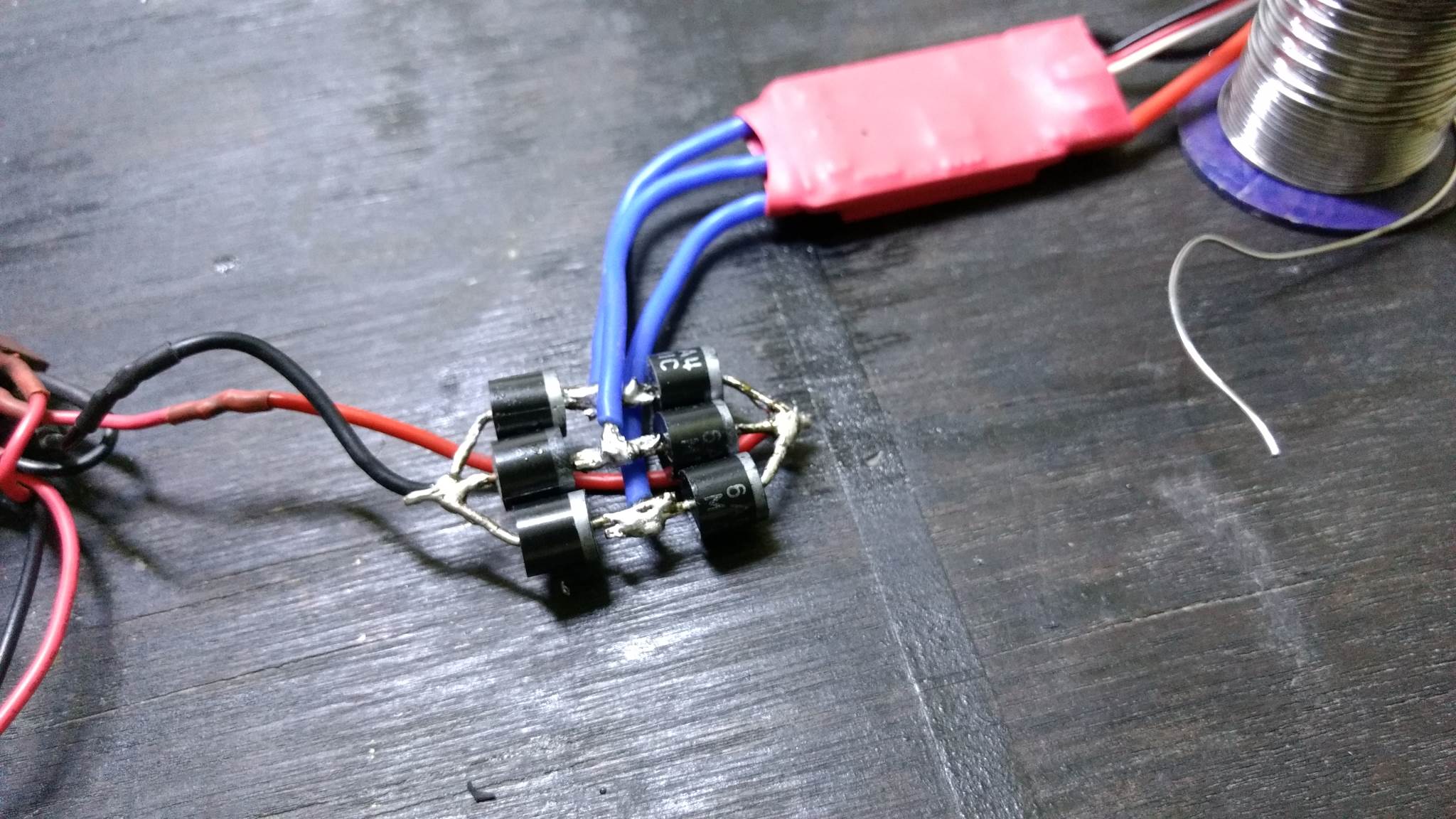
Three Phase Rectifier for converting a Brushless ESC to Brushed ESC

RC Car with Front and Rear Suspension and DC Motor that is driven by a Three Phase Rectifier moded BLDC ESC
LINKS
Git >> https://github.com/arnabdasbwn
Follow me on Instagram >> https://www.instagram.com/arnabdasbwn/
Follow me on Twitter >> https://twitter.com/ArnabDasBwn
Subscribe to my YouTube Channel >> https://www.youtube.com/c/ArnabDasBwn
Credits: Wikipedia

9 Comments
Brian · October 5, 2018 at 1:05 pm
Very cool and informative. I’m doing a different project in turn wanting to design and assemble a project esc to drive a bldc motor as a high speed miniature spindle controlled by a motion board using a digital pot and oscillator to control the speed via a 0-5v signal. This is very challenging in an area I haven’t experience with so I am doing the research and landed here to learn some useful information regarding my research. My other option is to utilize an existing esc and manage the controls at the front side however this is less desirable where I’d prefer a clean open circuit on one specific board mounted in an enclosure. Thank you for your post.
Akash · September 22, 2019 at 11:55 pm
Very good project sir .I have an query that it rotates only in one direction or it is bidirectional and does it provide braking of motor.
Crazy Engineer · October 16, 2019 at 12:58 am
It Moves Bidirectional and It Doesn’t provide braking.
Vinit · November 17, 2019 at 2:34 pm
Can IN4007 diodes be used for this??
Is this 100% working??
Crazy Engineer · November 22, 2019 at 12:57 am
No, IN4007 will not be able to Handel the Current.
HITESH R PATEL · February 2, 2020 at 8:36 am
how can can its work bidirectional, as rectifier out put never change
Crazy Engineer · February 13, 2020 at 10:11 pm
You have to swap the terminals using a DPDT Switch. And control the DPDT Switch with a Servo motor.
Cliff · May 29, 2020 at 8:33 pm
Or use a DPDT relay switch whose switching mechanism is controlled by an electrical signal sent to the solenoid instead of via the mechanical means of a servo.
Crazy Engineer · June 2, 2020 at 5:13 pm
There are even better way to do this by using MOSFETs and Logic Circuits to control the direction. This is just an chep and immediate solution.