Introduction : Arduino 8×8 LED Matrix FreeForm Circuit Design | ULN2803APG | 74HC595N
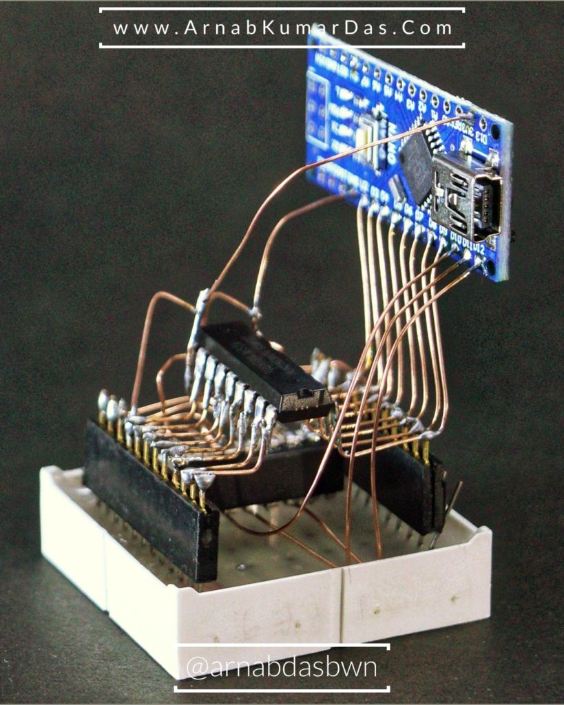
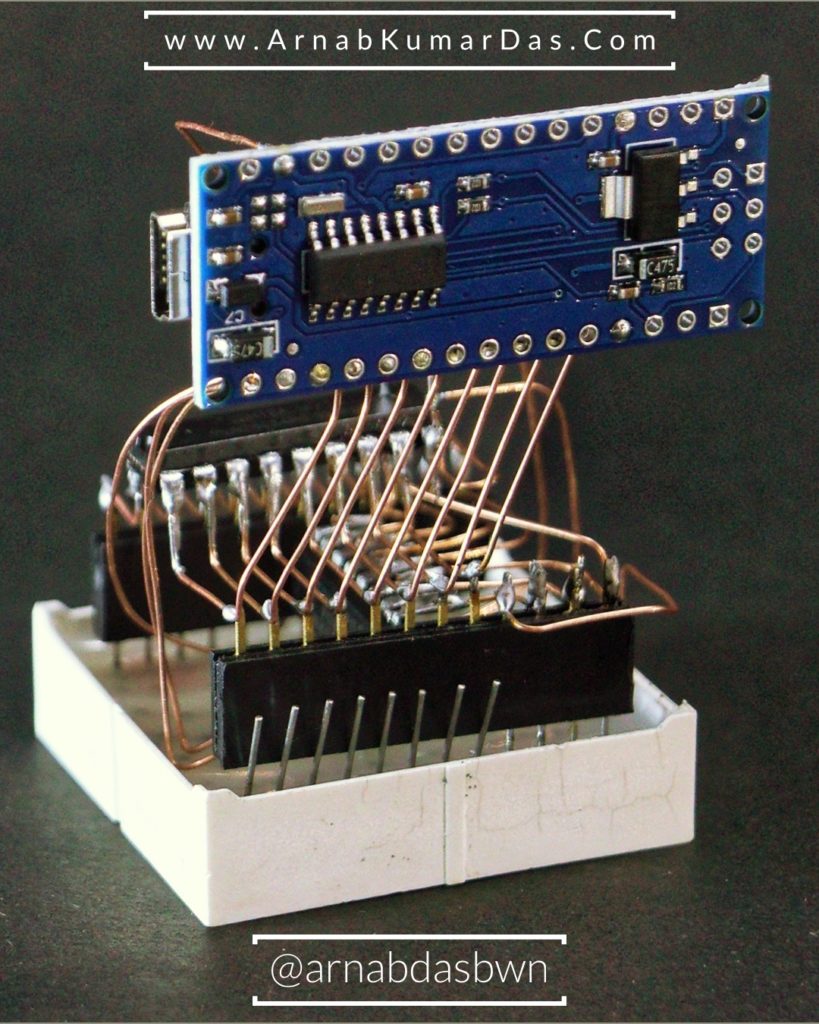
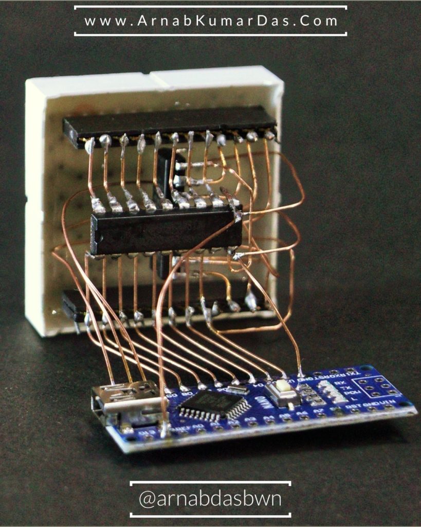
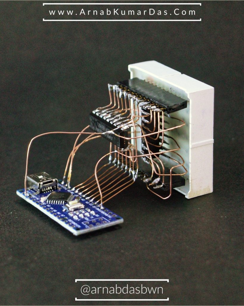
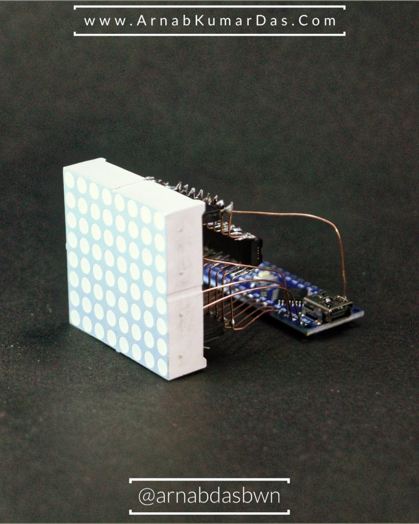
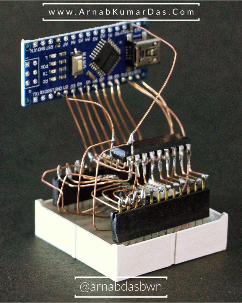
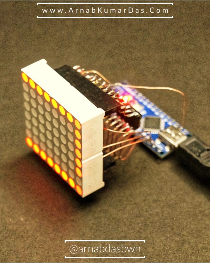
This Project is a different and unique as it uses FreeForm Circuit Design / Circuit Sculpturing i.e. Circuit Design without the use of any PCB. The LED Matrix Displays patterns/frames saved in the memory of Arduino UNO. [ You can download the complete Project at the
Project BOM
Click on Each Product Below and You will be Taken to the Product Page that I trust and have used in my Project. I Highly Recommend You Buy Directly from the Link Below or Add to Cart.
- Arduino Nano as the Microcontroller
- ULN2803APG as the Darlington Pair Current Sink
- 74HC595N as the Shift Register
- 8 X 8 LED Matrix [ Common Cathode ]
- Non-Insulated Copper / Brass Wire of 22AWG
Lets Make it
Time needed: 4 hours
Steps to Build the 8 x 8 LED Matrix FreeForm Display
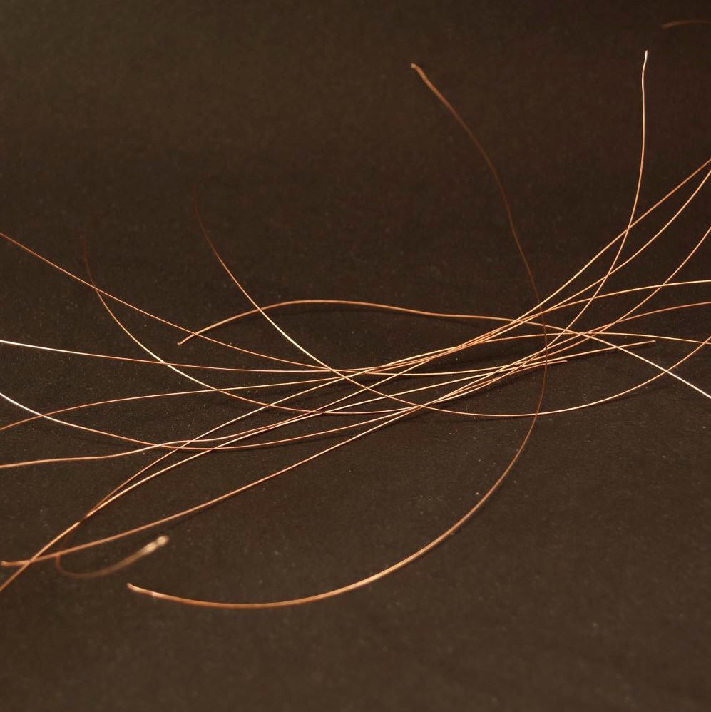
- Extracting the Copper Wires
I extracted the Copper Wires from an old Ethernet Cable. Usually Cat 5 / 6 will have Copper Wires of 24AWG to 28AWG. You can also buy from local electrical store but as these are non insulated it is difficult to find.

- Soldering Setup
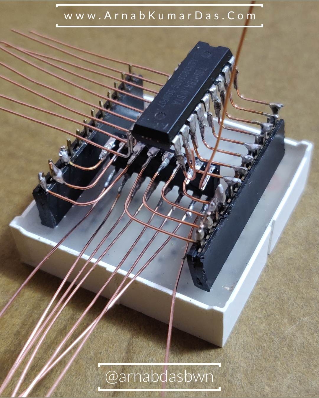
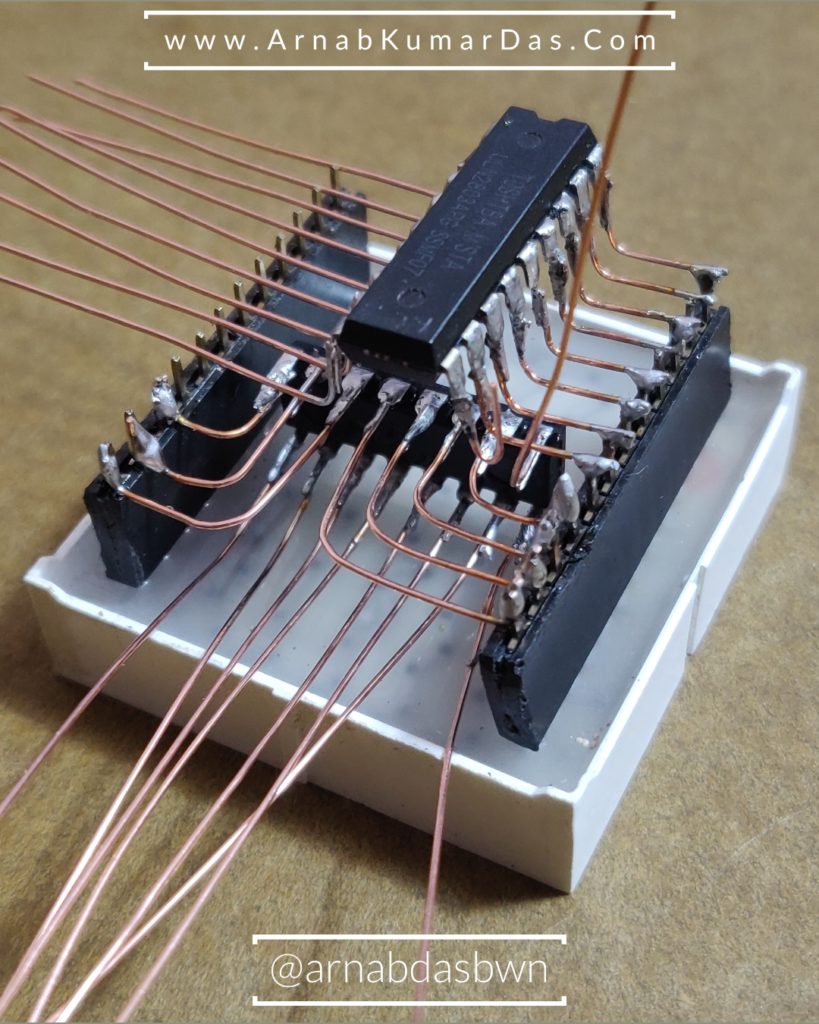
The wires need to be soldered to the ICs and for a good shiny solder, the ICs need to properly hold in place. I was not having a third helping hand so I made my own. I Used a C-Clamp with a Twizzer to hold the IC in Place.

- Plan the Routing of Wires
Start with one Component and keep adding the other Components to it you will naturally get ideas how to route the wires and will end up into a beautiful design. [ Schematic is
provided below ]
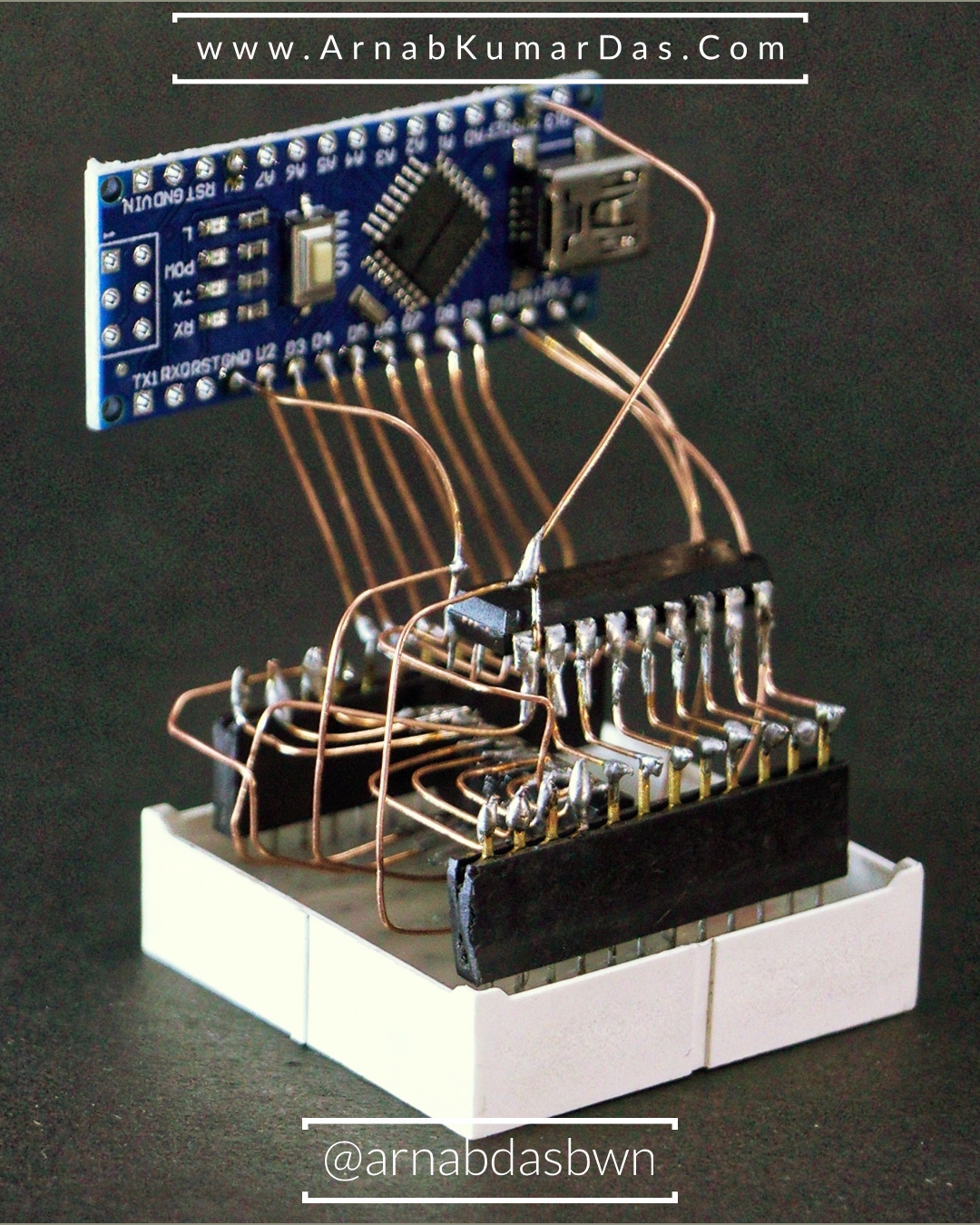
- Flash the Code in the Arduino
The last component I added to the circuit was the Arduino Nano. I used Arduino Nano as it kept the form factor small and it is cheap. [ Code is Provided Below ]

Arduino IDE Source Code
//
// Code is Provided by www.ArnabKumarDas.com
// Code should not be used for System Crticial Application which may lead to loss of life
// Code is for Demostraction or POC Purpose Not for Production
//
const byte IMAGES[][8] = {
  {
    B11111111,
    B10000001,
    B10000001,
    B10000001,
    B10000001,
    B10000001,
    B10000001,
    B11111111
  }, {
    B11111111,
    B10000001,
    B10000001,
    B10000001,
    B10000001,
    B10000001,
    B10000001,
    B11111111
  }
};
const int IMAGES_LEN = sizeof(IMAGES) / 8;

uint8_t colPins[8] = { 2, 3, 4, 5, 6, 7, 8, 9};

#define SCK_PIN 10
#define RCK_PIN 11
#define SER_PIN 12

void setup() {
  // Turn everything to low
  for (int i = 0; i < 8; i++) {
    pinMode(colPins[i], OUTPUT);
  }
  pinMode(SER_PIN, OUTPUT);
  pinMode(SCK_PIN, OUTPUT);
  pinMode(RCK_PIN, OUTPUT);
  Serial.begin(9600);
}

void loop()
{
  for ( int i = 0; i < IMAGES_LEN; i++)
  {
    for (int j = 0; j < 20 ; j++)
    {
      for (int column = 0; column < 8; column++)
      {
        digitalWrite(colPins[column], HIGH);  //columnbits & (1 << column) ? HIGH : LOW);
        write595(IMAGES[i][column] << 4 | IMAGES[i][column] >> 4 ); // prepare to write the row
        delay(1);
        write595(0);
        for (int k = 0; k < 8; k++)
          digitalWrite(colPins[k], LOW); // Cleanup cols
      }
    }
  }
}

void write595(byte data)
{
  digitalWrite(RCK_PIN, LOW);
  shiftOut(SER_PIN, SCK_PIN, MSBFIRST, data);
  digitalWrite(RCK_PIN, HIGH);
}
Schematic
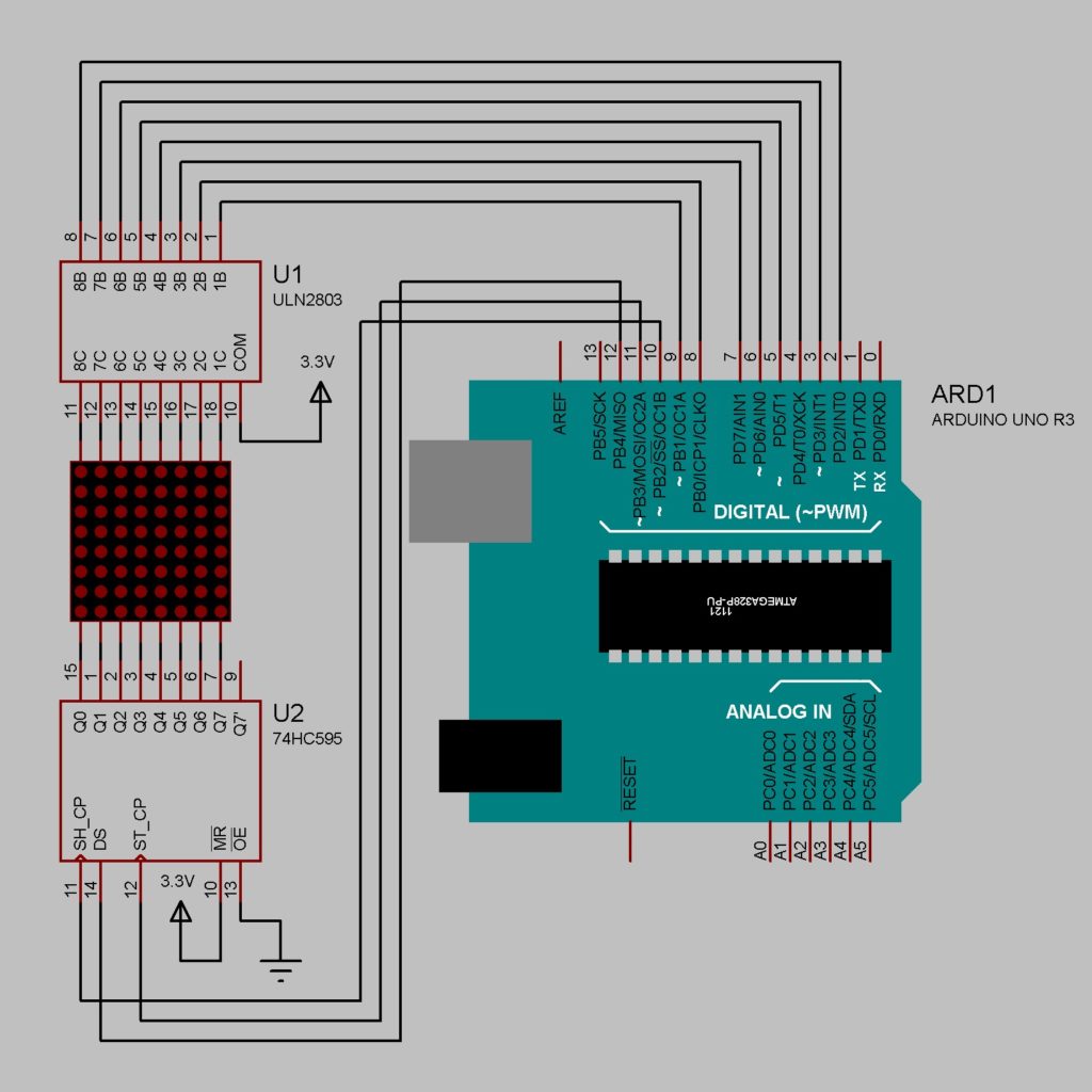

Arduino Shift Register 8×8 LED Matrix ULN2803APG 74HC595N 
Arduino 8×8 LED Matrix ULN2803APG 74HC595N 
Arduino Nano 8×8 LED Matrix ULN2803APG 74HC595N 
Arduino 8×8 LED Matrix ULN2803APG 74HC595N 
Arduino 8 x 8 LED Matrix Tutorial 
Arduino Circuit Sculpture / FreeForm Circuit 
FreeForm Circuit Design Circuit Sculpture 
LED Matrix 8 x 8 Arduino Ciruit Sculpture
Download Project
Thank You for Reading You are
Happy Making and Hacking 😊
Liked this content? Please Subscribe / Share to support this Website! 😇

2 Comments
BEGUE · January 22, 2020 at 10:09 am
Magnifique travail, parfaitement bien documenté. Un grand bravo !
Crazy Engineer · January 29, 2020 at 3:12 pm
Thank You So Much