Description
Specification of PID Line Follower Code
- Only the firmware is supplied through email or online download, with no accompanying hardware kit
- Algorithm: Proportional Integral Differential Algorithm (PID)
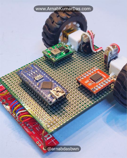
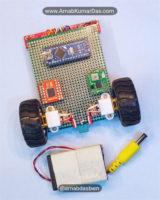
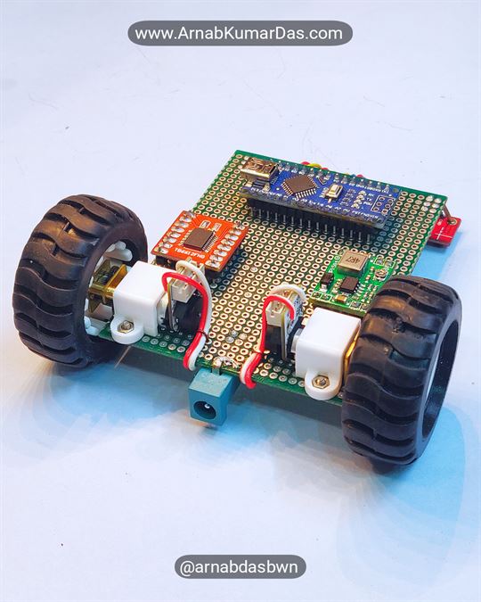
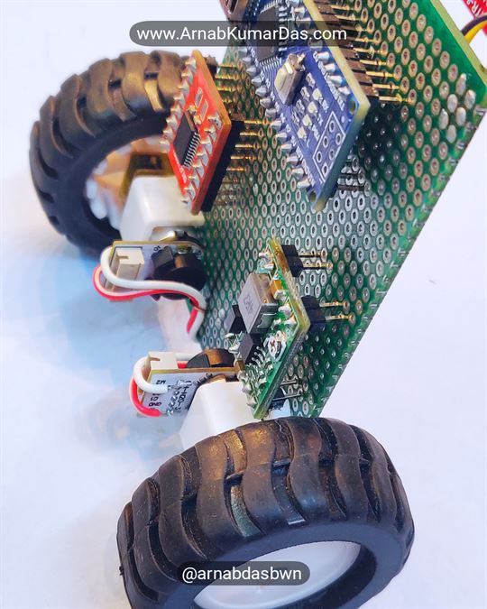
- Microcontroller Supported: ATmega328P or Arduino UNO/NANO/MINI
- Sensor Support: QTR-8RC Sensor
- Special Feature: Auto Sensor Calibration, PWM Based Motor Control for Smooth Operation
- IDE Support: Atmel Studio Project and Arduino IDE Project
- Motor Driver Support: Dual Channel Motor Driver Support e.g. L293D, L298, TB6612FNG
- Motor Speed Support: Maximum 800RPM at 4cm Wheel Diameter for High Speed Code
- Maximum Robot Speed: 3 meters per second [m/s] for High Speed Code
- Tutorial: Step By Step Guide
Code / Software Description
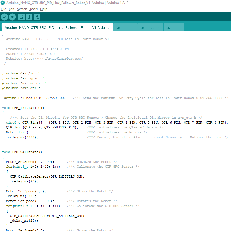
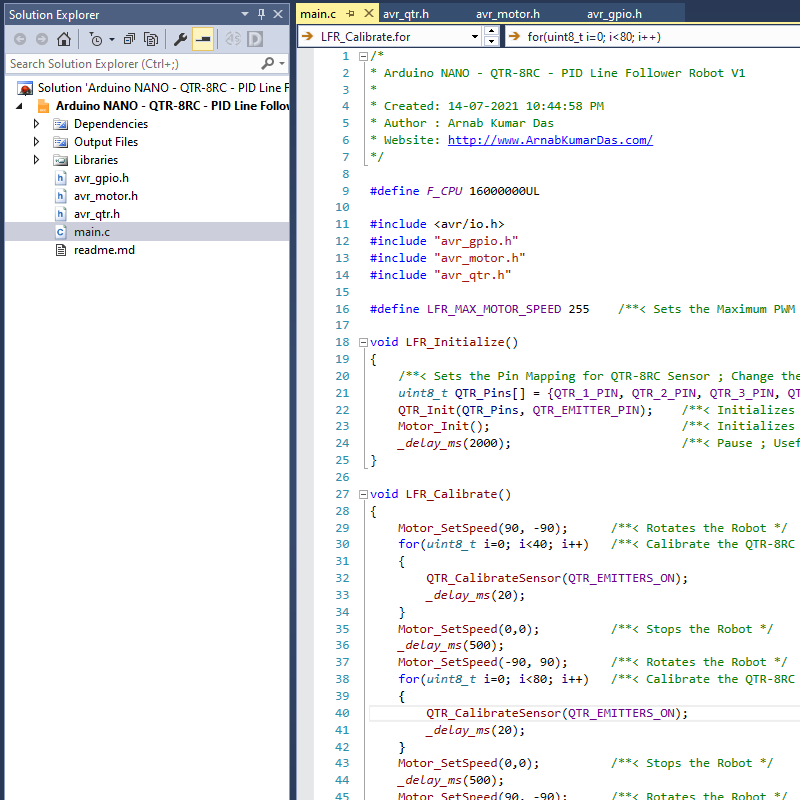
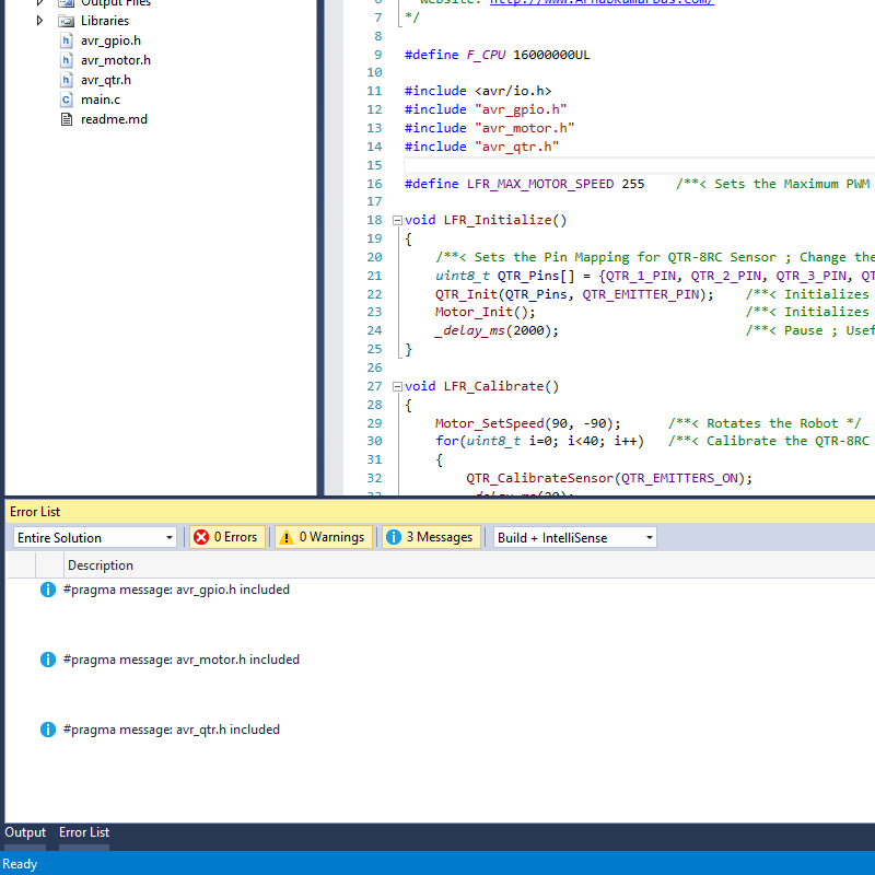
The code for the Arduino Line Follower Robot is available in Arduino IDE as well as Atmel Studio. It is recommended to use Atmel Studio as it is more professional and provides official support.
The firmware project has three library files avr_gpio.h , avr_qtr.h , avr_motor.h and one main.c file. The library file code is written at the AVR register level. The library files are all well documented. The APIs exposed can be used in both Arduino IDE and Atmel Studio. The programming language used in C.
You can learn more about Register Level Programming in Embedded C Programming Tutorial.
/** @name QTR_CONTROL
 *  Public Functions to Control QTR Sensor
 */
void QTR_Init(uint8_t *SensorPin, uint8_t EmitterPin);
void QTR_DeInit();
void QTR_Calibrate(uint16_t *CalibratedMinimum, uint16_t *CalibratedMaximum, uint8_t ReadMode);
void QTR_CalibrateSensor(uint8_t ReadMode);
void QTR_ResetCalibration();
void QTR_ReadSensor(uint16_t *SensorValues, uint8_t ReadMode);
void QTR_ReadRaw(uint16_t *SensorValues);
void QTR_ReadCalibrated(uint16_t *SensorValues, uint8_t ReadMode);
int16_t QTR_ReadLine(uint16_t *SensorValues, uint8_t ReadMode);
void QTR_EmitterOn();
void QTR_EmitterOff();
/**@}*/
/** @name MOTOR_CONTROL
* Public Functions to Control Motor
*/
/**@{*/
void Motor_Init(void);
void Motor_DeInit(void);
void Motor_SetSpeed(int16_t M1Speed, int16_t M2Speed);
void Motor_SetSpeedM1(int16_t M1Speed);
void Motor_SetSpeedM2(int16_t M2Speed);
/**@}*//** @name GPIO_GLOBAL_PULL_UP_CONTROL
* Public Functions to Control Global GPIO Pull Up
*/
/**@{*/
inline void GPIO_DisableGlobalPullUp();
inline void GPIO_EnableGlobalPullUp();
/**@{*/
/** @name GPIO_CONFIGURATION
* Public Functions to Configure GPIO as Digital I/O
*/
/**@{*/
inline void GPIO_Init(volatile uint8_t *Port, uint8_t Pin, uint8_t PinMode);
inline void GPIO_InitPin(uint8_t Pin, uint8_t PinMode);
inline void GPIO_DeInit(volatile uint8_t *Port, uint8_t Pin);
inline void GPIO_DeInitPin(uint8_t Pin);
/**@{*/
/** @name GPIO_PIN_READ_WRITE
* Public Functions to Read and Write Digital I/O Pin
*/
/**@{*/
inline uint8_t GPIO_Read(volatile uint8_t *Port, uint8_t Pin);
inline uint8_t GPIO_ReadPin(uint8_t Pin);
inline void GPIO_Write(volatile uint8_t *Port, uint8_t Pin, uint8_t PinState);
inline void GPIO_Toggle(volatile uint8_t *Port, uint8_t Pin);
inline void GPIO_WritePin(uint8_t Pin, uint8_t PinState);
inline void GPIO_WritePinLow(uint8_t Pin);
inline void GPIO_WritePinHigh(uint8_t Pin);
inline void GPIO_WritePinToggle(uint8_t Pin);
/**@{*/PID Line Follower Robot Code Walkthrough
The first few lines of code in the function ” main()” declares all the variables needed for the PID algorithm.
	uint16_t LFR_SensorValue[8];       /**< Array to Save Raw IR Sensor values of QTR-8RC */
	uint16_t LFR_Position = 0;         /**< Variable to Save the QTR-8RC Sensor Position */
	int16_t  LFR_Proportional = 0;     /**< Variable to Save the Proportional Output of PID Control Algorithm */
	int16_t  LFR_LastProportional = 0; /**< Variable to Save the Previous Proportional Output of PID Control Algorithm */
	int16_t  LFR_Derivative = 0;       /**< Variable to Save the Derivative Output of PID Control Algorithm */
	int64_t  LFR_Integral = 0;         /**< Variable to Save the Integral Output of PID Control Algorithm */
	int16_t  LFR_ControlOutput = 0;    /**< Variable to Save the Final Control Output of PID Control Algorithm */

	LFR_Initialize();                  /**< Function to Initialize all Peripherals */
	LFR_Calibrate();                   /**< Function to Calibrate QTR-8RC Sensor */
The function “LFR_Initialize()” initializes all used peripherals of the Arduino/ATmega328P. The QTR_X_PIN macros are defined in the avr_qtr.h file.
void LFR_Initialize()
{
/**< Sets the Pin Mapping for QTR-8RC Sensor ; Change the Individual Pin Macros in avr_qtr.h */
uint8_t QTR_Pins[] = {QTR_1_PIN, QTR_2_PIN, QTR_3_PIN, QTR_4_PIN, QTR_5_PIN, QTR_6_PIN, QTR_7_PIN, QTR_8_PIN};
QTR_Init(QTR_Pins, QTR_EMITTER_PIN); /**< Initializes the QTR-8RC Sensor */
Motor_Init(); /**< Initializes the Motors */
_delay_ms(2000); /**< Pause ; Useful to Align the Robot Manually if Outside the Line */
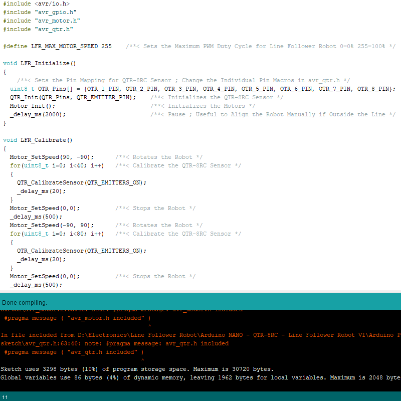
}The function “LFR_Calibrate()” calibrates the QTR-8RC line sensor. The robot rotates in the same place and calibrates the sensor with all possible sensor values sampled during this time.
void LFR_Calibrate()
{
	Motor_SetSpeed(90, -90);      /**< Rotates the Robot */
	for(uint8_t i=0; i<40; i++)   /**< Calibrate the QTR-8RC Sensor */
	{
		QTR_CalibrateSensor(QTR_EMITTERS_ON);
		_delay_ms(20);
	}
	Motor_SetSpeed(0,0);          /**< Stops the Robot */
	_delay_ms(500);
	Motor_SetSpeed(-90, 90);      /**< Rotates the Robot */
	for(uint8_t i=0; i<80; i++)   /**< Calibrate the QTR-8RC Sensor */
	{
		QTR_CalibrateSensor(QTR_EMITTERS_ON);
		_delay_ms(20);
	}
	Motor_SetSpeed(0,0);          /**< Stops the Robot */
	_delay_ms(500);
	Motor_SetSpeed(90, -90);      /**< Rotates the Robot */
	for(uint8_t i=0; i<40; i++)   /**< Calibrate the QTR-8RC Sensor */
	{
		QTR_CalibrateSensor(QTR_EMITTERS_ON);
		_delay_ms(20);
	}
	Motor_SetSpeed(0,0);          /**< Stops the Robot */
	_delay_ms(2000);              /**< Pause ; Useful to Realign the Robot Manually if Outside the Line */
}
The infinite while loop below is responsible for the PID algorithm. The current gains Kp=1/10, Ki=1/10000, and Kd=3/2 should make the Line Follower Robot work out of the box if a similar construction is done. It is good to note that PID coefficients depend heavily on physical parameters like the size of the robot, weight, proportions, battery voltage, friction, etc. It is always advised to tune your robot after any hardware change.
	while(1)
	{
	    LFR_Position = QTR_ReadLine(LFR_SensorValue, QTR_EMITTERS_ON);    /**< Reads the QTR-8RC Line Sensor to Get the Line Position */
		LFR_Proportional = LFR_Position - QTR_LINE_MID_VALUE;             /**< Computes the Proportional Output of PID Control Algorithm */
		LFR_Derivative = LFR_Proportional - LFR_LastProportional;         /**< Computes the Derivative Output of PID Control Algorithm */
		LFR_Integral += LFR_Proportional;                                 /**< Computes the Integral Output of PID Control Algorithm */
		LFR_LastProportional = LFR_Proportional;                          /**< Saves the Old Proportional Output of PID Control Algorithm */

		LFR_ControlOutput = LFR_Proportional/10 + LFR_Integral/10000 + LFR_Derivative*3/2;    /**< Computes the Final Control Output of PID Control Algorithm */

		if(LFR_ControlOutput > LFR_MAX_MOTOR_SPEED)
		{
			LFR_ControlOutput = LFR_MAX_MOTOR_SPEED;    /**< Keeps The Motor Speed in Limit */
		}
		if(LFR_ControlOutput < -LFR_MAX_MOTOR_SPEED)
		{
			LFR_ControlOutput = -LFR_MAX_MOTOR_SPEED;    /**< Keeps The Motor Speed in Limit */
		}

		if(LFR_ControlOutput < 0)
		{
			Motor_SetSpeed(LFR_MAX_MOTOR_SPEED + LFR_ControlOutput, LFR_MAX_MOTOR_SPEED);    /**< Drives the Motor According to the Control Output */
		}
		else
		{
			Motor_SetSpeed(LFR_MAX_MOTOR_SPEED, LFR_MAX_MOTOR_SPEED - LFR_ControlOutput);    /**< Drives the Motor According to the Control Output */
		}
	}
The speed of the line follower robot is controlled by the macro LFR_MAX_MOTOR_SPEED . It is advised to recalibrate the robot at a higher speed for optimum performance.
#define LFR_MAX_MOTOR_SPEED 255 /**< Sets the Maximum PWM Duty Cycle for Line Follower Robot 0=0% 255=100% */Programming The Arduino Nano Line Follower Robot
The project folder has all the required files. If you use Arduino IDE then open the Arduino project folder and flash the Arduino Nano from Arduino IDE. If you use Atmel Studio then open the Atmel Studio project present inside the Atmel Studio folder and flash using your preferred programmer. The Firmware Image folder has prebuilt firmware that can be flashed directly to the Arduino Nano.
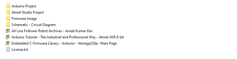 Arduino Line Follower Robot Project Structure
Line Follower Robot Atmel Studio Project
Line Follower Robot Arduino Project
Schematics
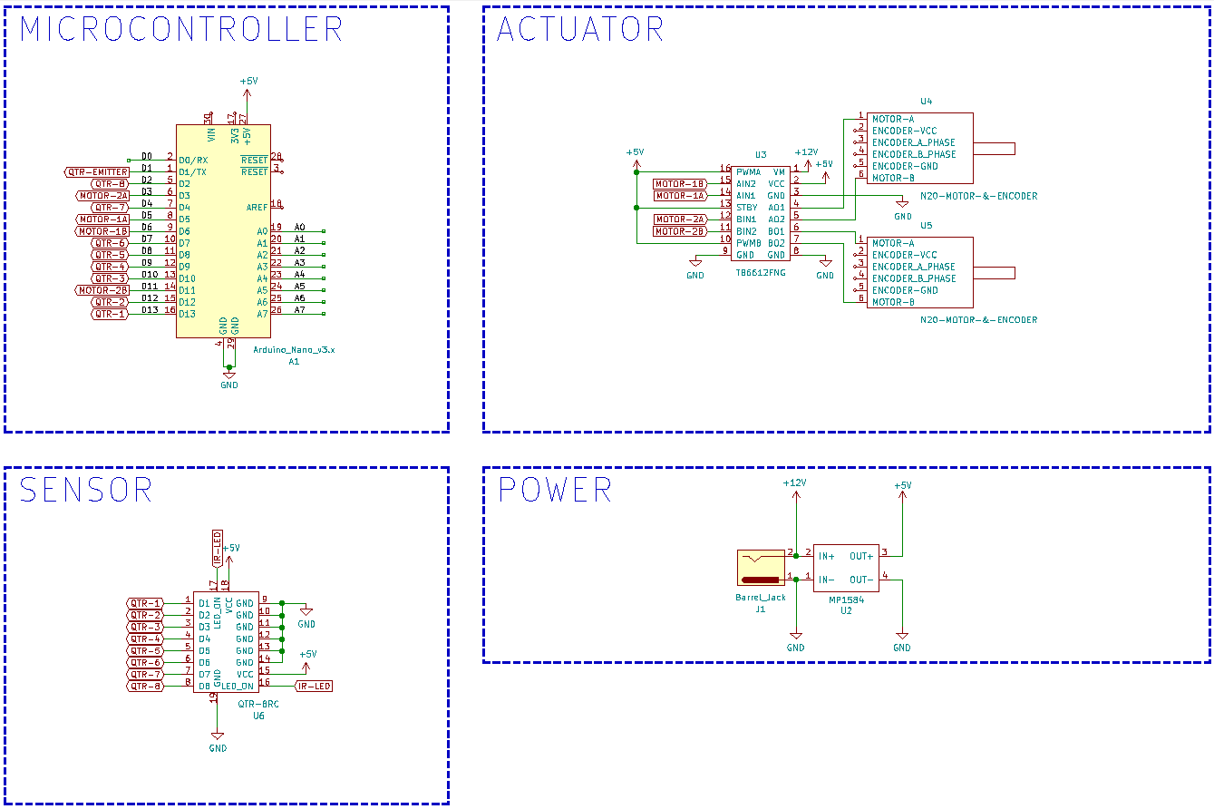
Arduino NANO – QTR-8RC – Line Follower Robot Schematic / Circuit Design

Reviews
There are no reviews yet.