Introduction
This project is a continuation of the version 1 of the Drawing Machine I built a year ago. The previous Drawing Machine I build was based on T-Bot design. It had some disadvantages like it was heavy, cantilever-like design which gave it a swinging action that used to distort the drawing, and it was slow. So I decided to make some improvements in version 2.
https://www.arnabkumardas.com/cnc.html

Project Bill of Material
Click on Each Product Below and You will be Taken to the Product Page that I trust and have used in my Project. I Highly Recommend You Buy Directly from the Link Below or Add to Cart.
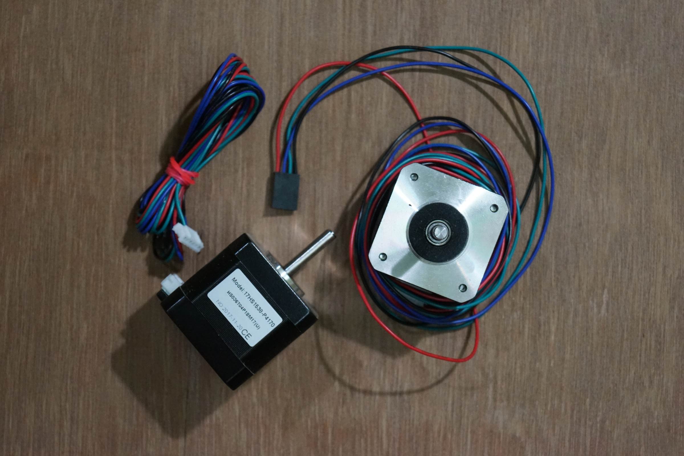
• 2 x NEMA 17 Steppers 1.8 Degree Step 12v Torque more than 4kg/cm
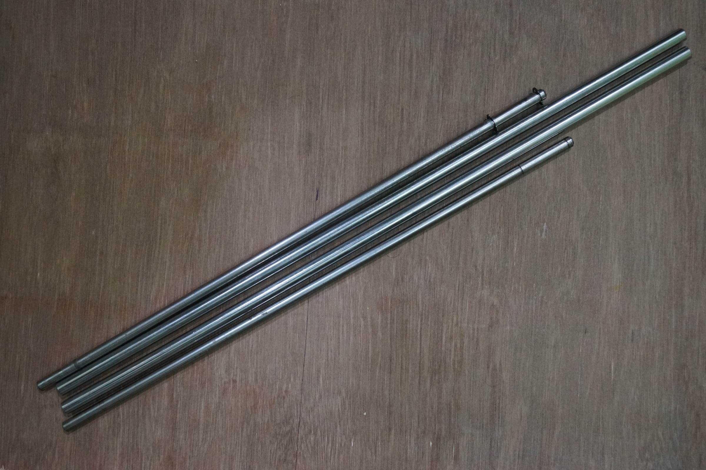
• 2 x 8mm Stainless Steel Smooth Rods
• 2 x 10mm Stainless Steel Smooth Rods
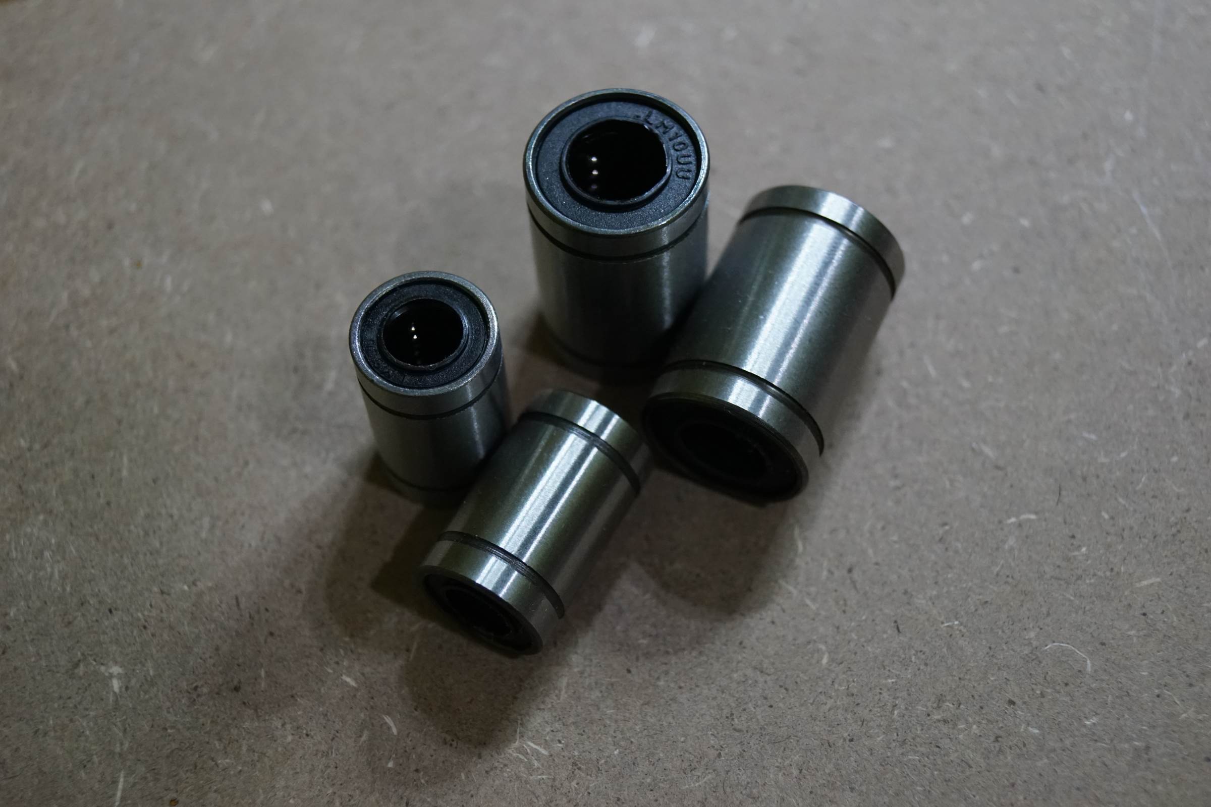
• 2 x LM8UU 8mm Linear Bearing or SC8UU 8mm Linear Bearing
• 4 x SK8 8mm Rod End Support
• 4 x LM10UU 10mm Linear Bearing or SC10UU 10mm Linear Bearing
• 2 x SK10 10mm Rod End Support
• 2 x 20-Tooth GT2 pulleys
• 12 x F623ZZ Bearings
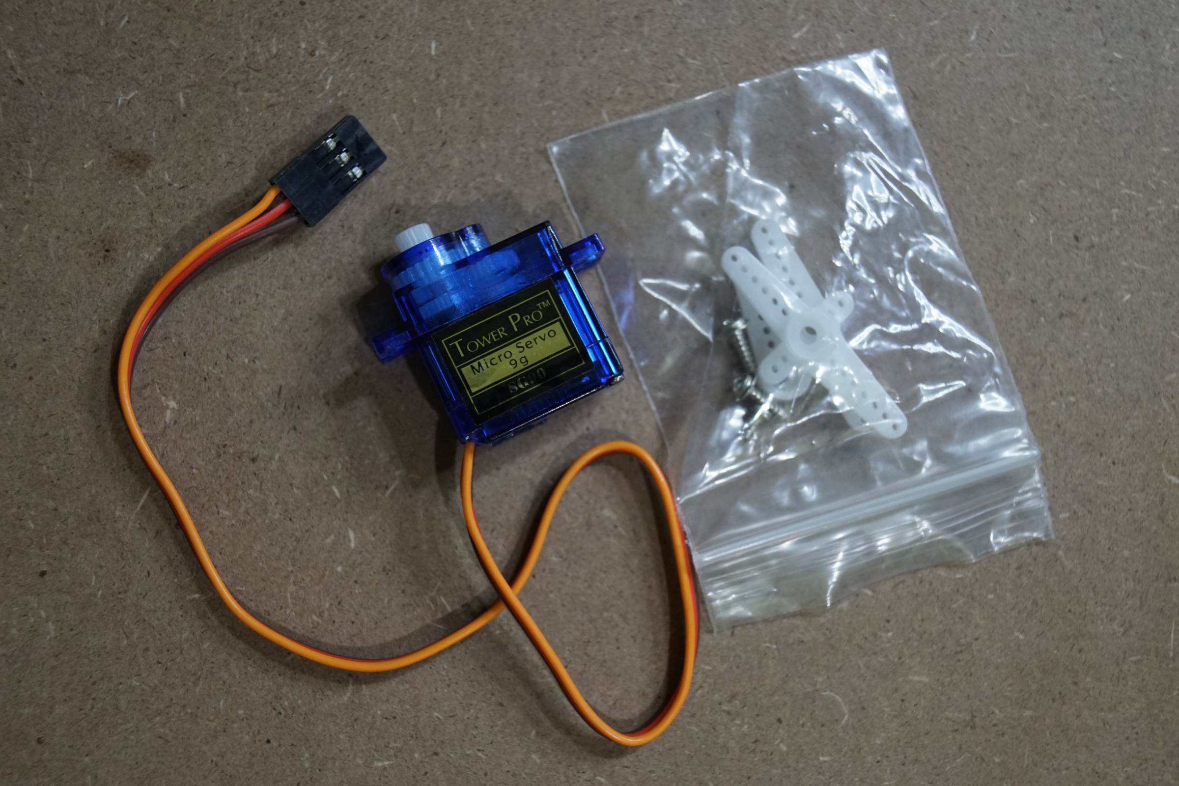
• 1 x Micro Servo SG90
• 1 x Arduino UNO
• 1 x CNC Shield V3
• 2 x Pololu Step Sticks A4988 Stepper Driver
• 1 x GT2 Belt (3 meters long)
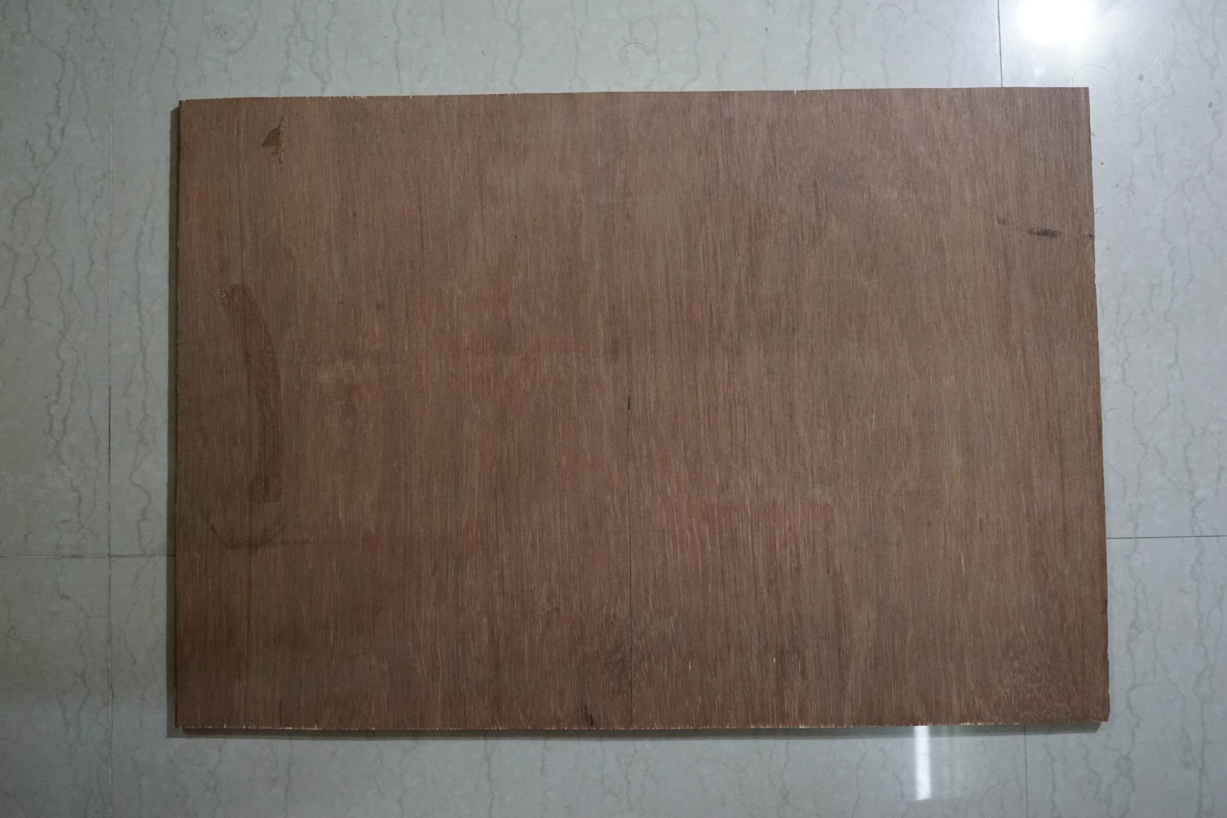
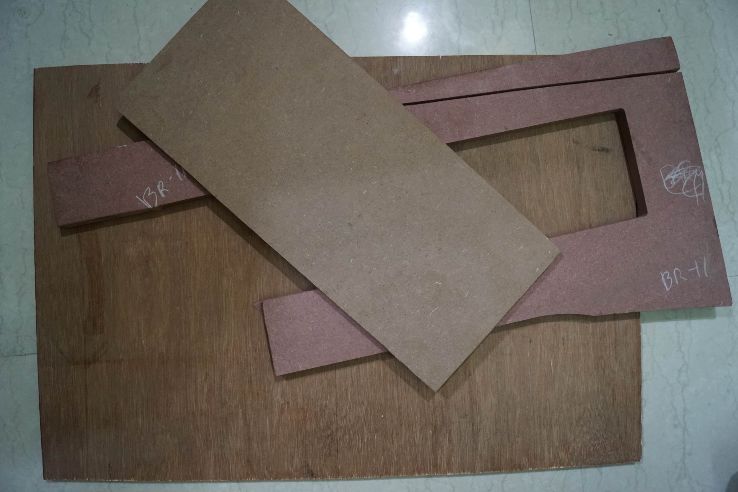
• 1 x Hard Wood Ply 50cmx60cmx1.5cm
• Multiple screws with nuts
• 1 x Wire 5m
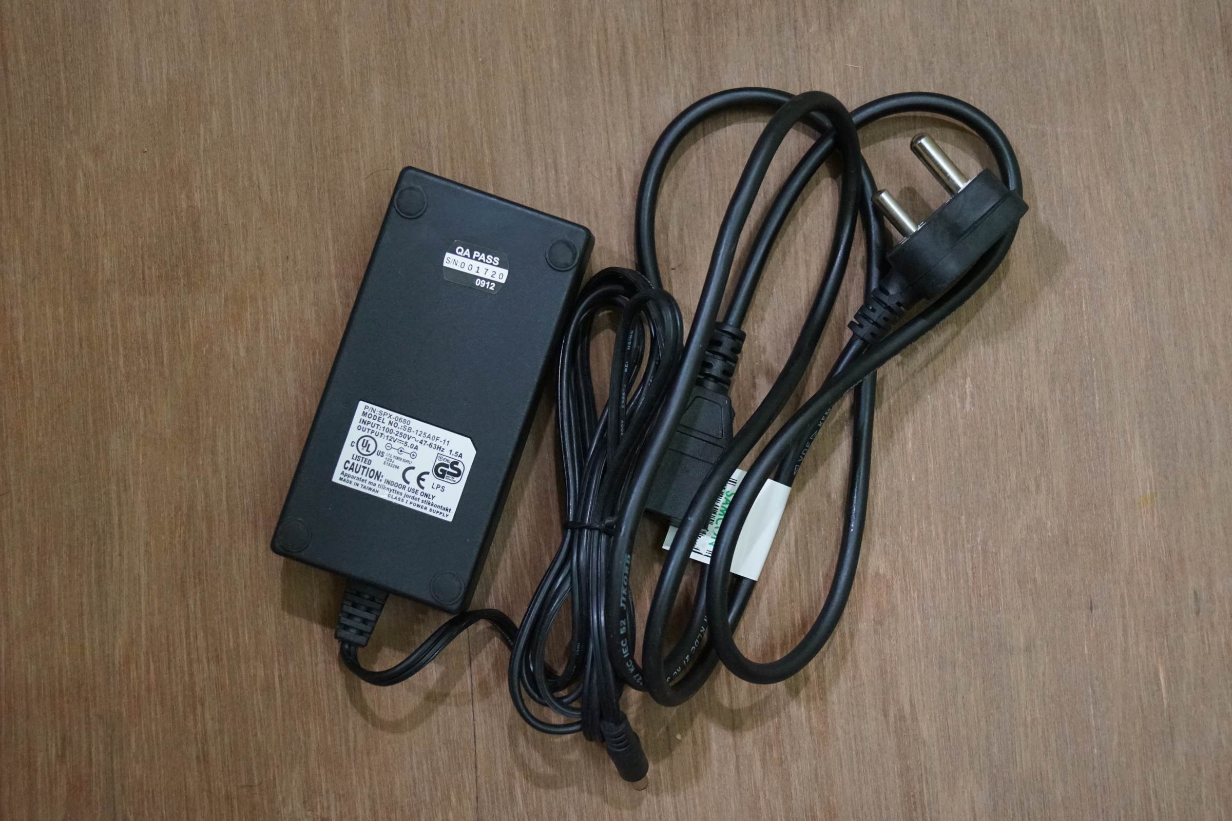
• 1 x SMPS 12v 5A
• 1 x Soldering Wire
• 1 x Solder
• 1 x Jig Saw
• 1 x Jig Saw Blade for wood cutting
• 1 x USB Wire
• 4 x Special Liquid ink PEN of multiple colours
• Miscellaneous Tools and Components
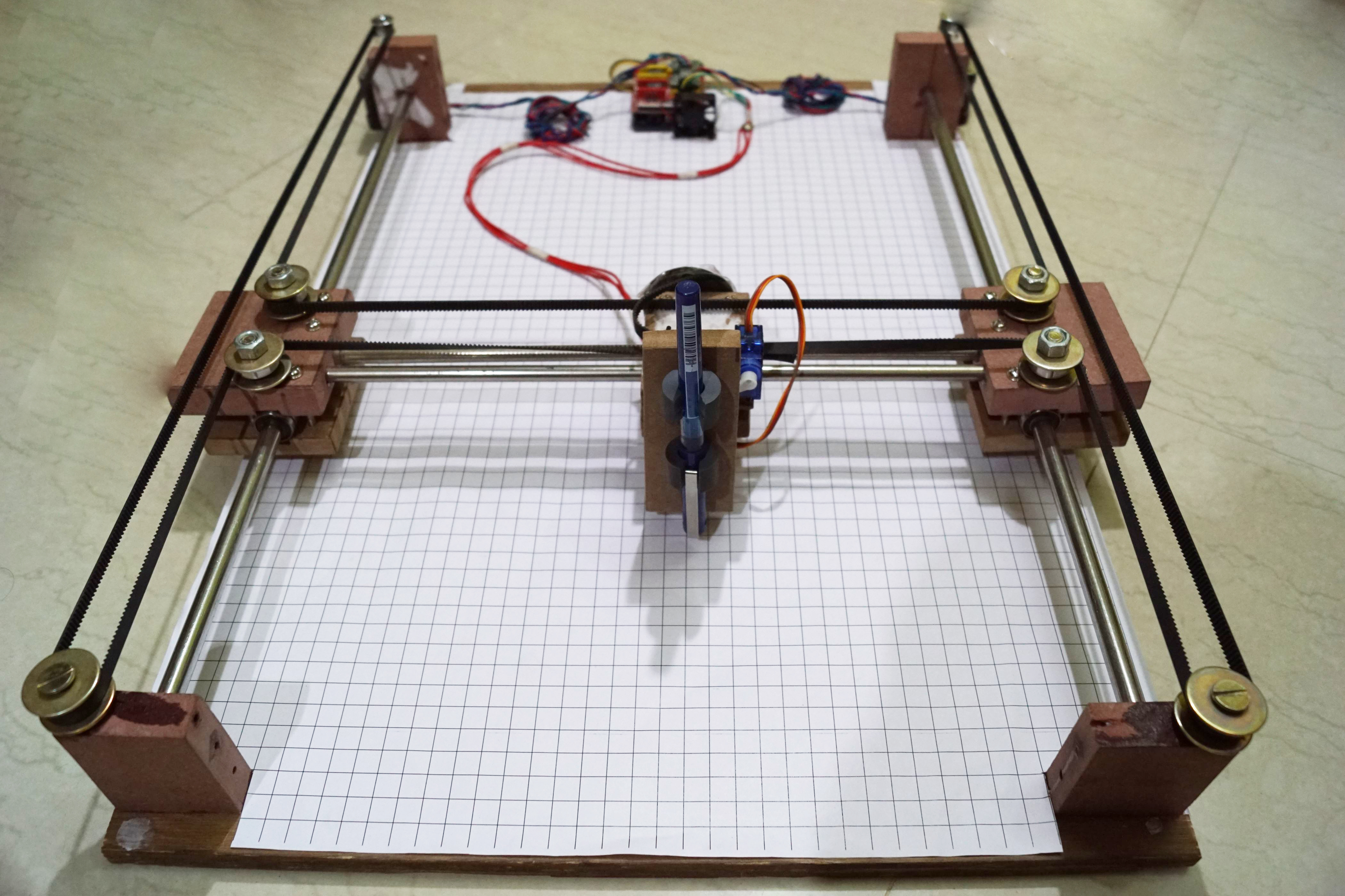
H-Bot Mechanics
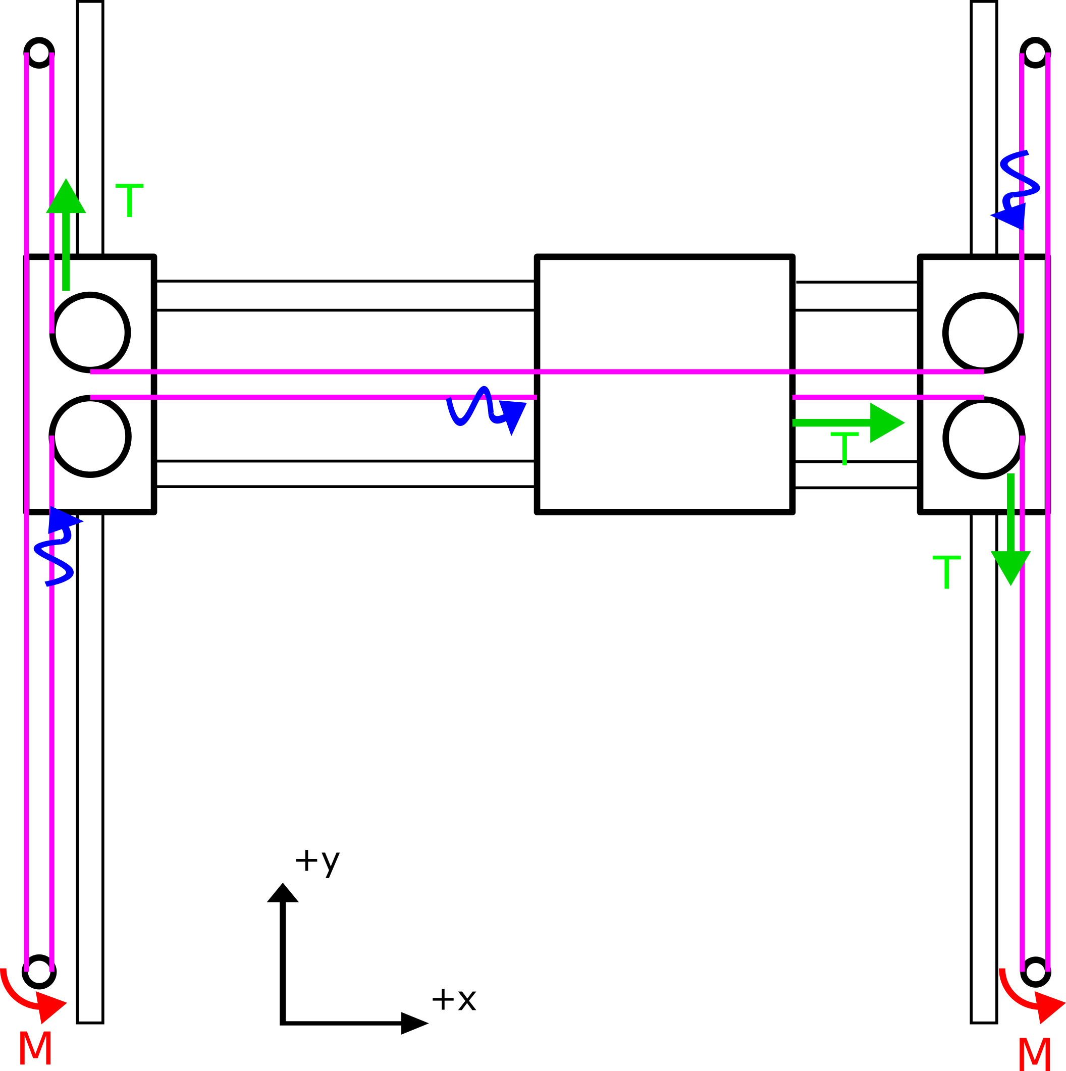
Why H-Bot? Because it has few advantages that made me choose it. It is cheap to construct as it needs less bearings and other materials, simple, clean and
Construction
Time needed: 2 days
Steps for building the Arduino Drawing Machine
- 50cm x 60cm Ply Wood for Drawing Machne’s Base

- 17HS1538 Stepper Motor
- Micro Servo Motor 9G
- 12V 5A SMPS Power Supply
- LM10UU and LM8UU Linear Bearing
- 8mm and 10mm Stainless Steel SS Smooth Rods
- MDF Board for other Parts
- Grid Paper for pasting on Ply Wood and MDF Boards for easy cutting
- Mockup to finalize position before drilling holes / cutting

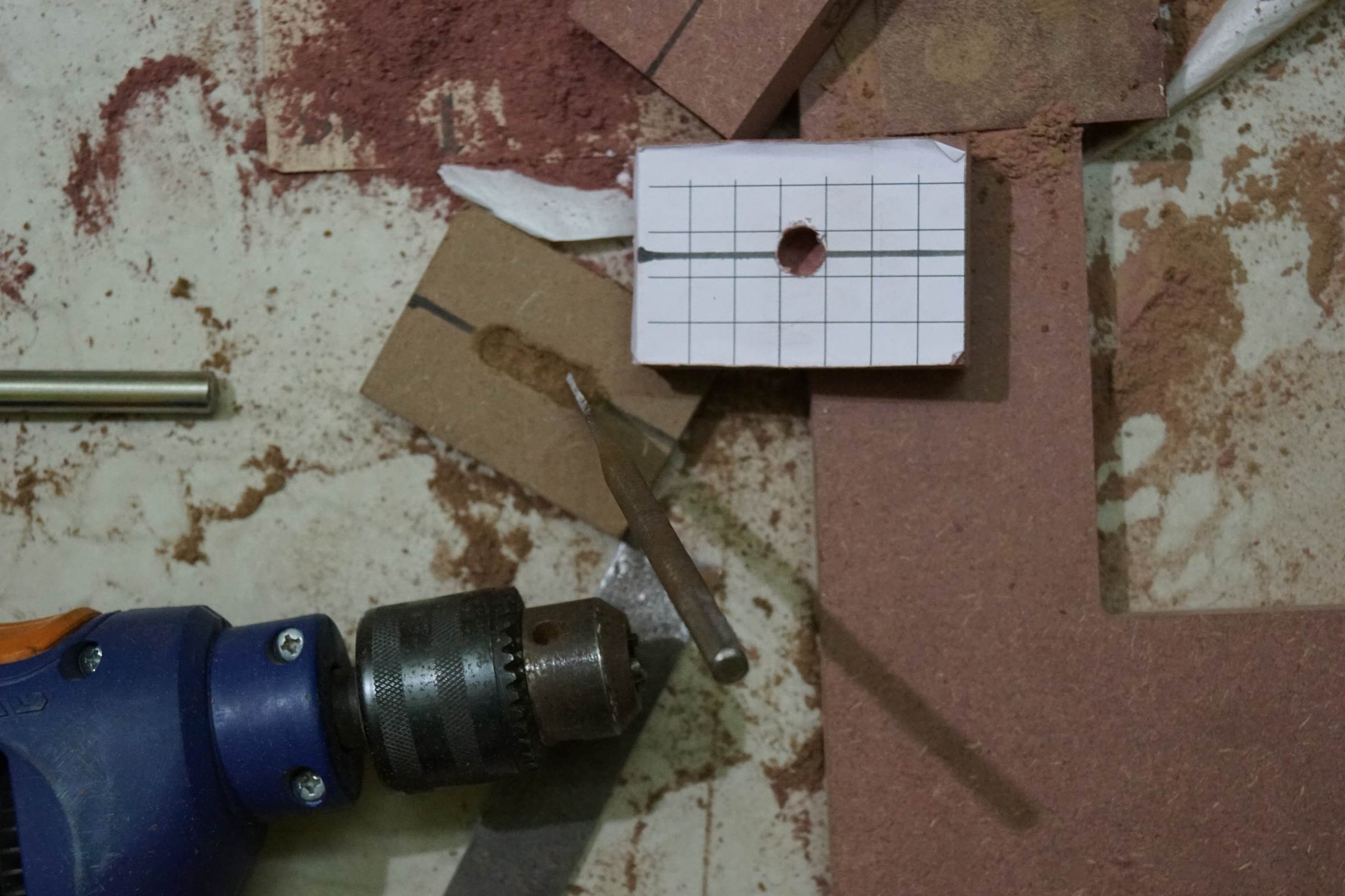
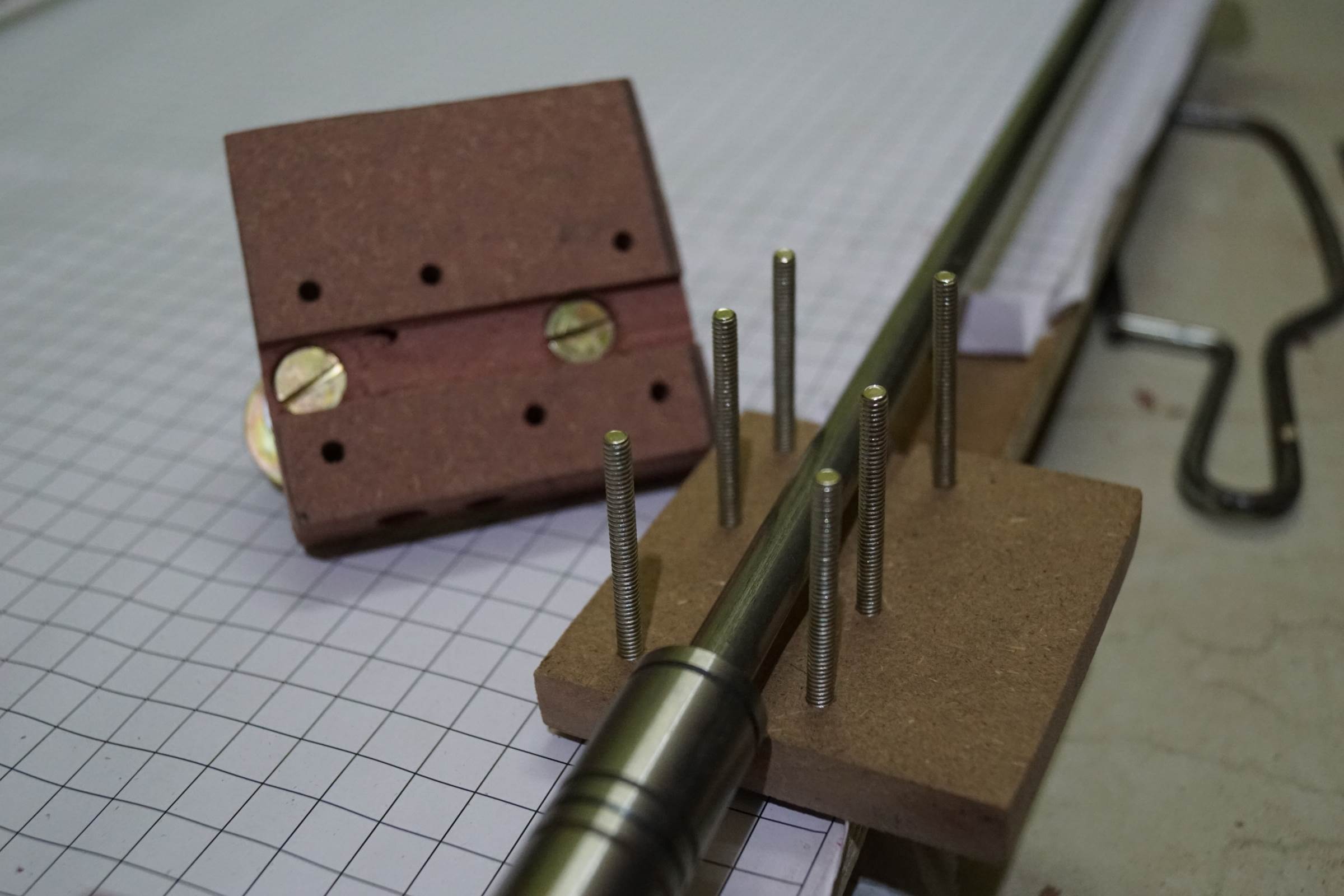
- Small pieces of MDF Board covered with Grid Paper for Axes Joints and Linear Bearing Holder
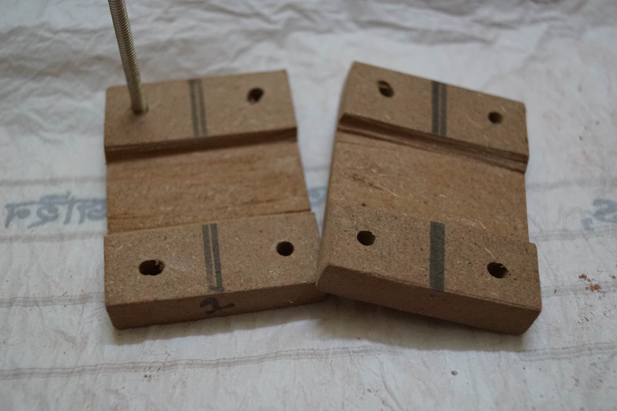
- 10mm Half Depth Drill was done on 4 pieces of MDF Board on
same point to make them end support for the two Y-Axis 10mm rods - End Support for 10mm Y Axis rod
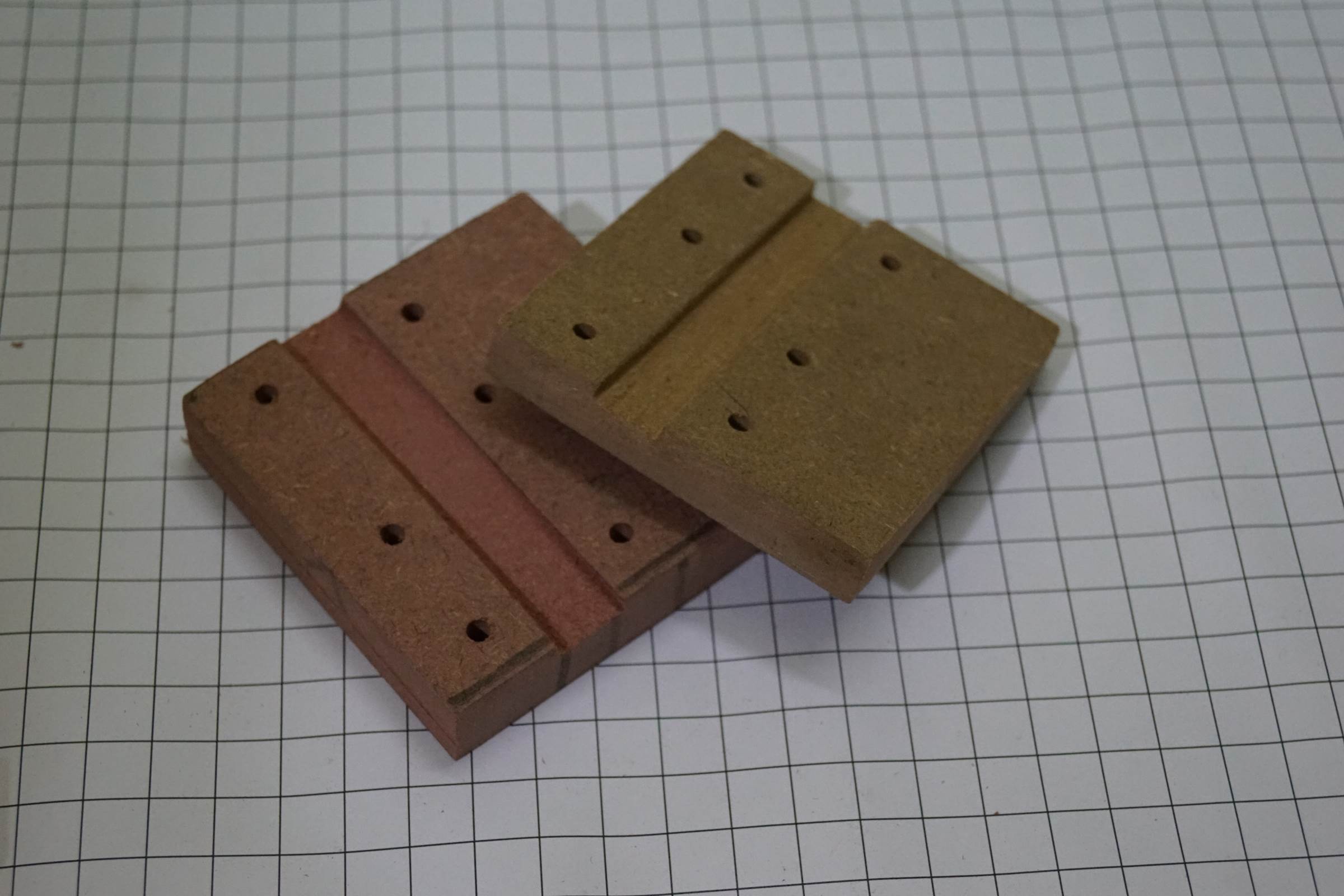
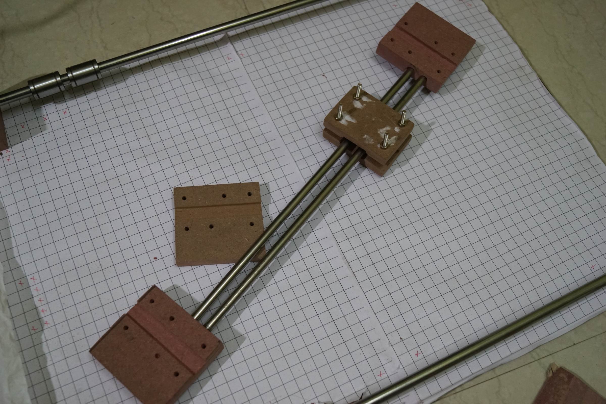
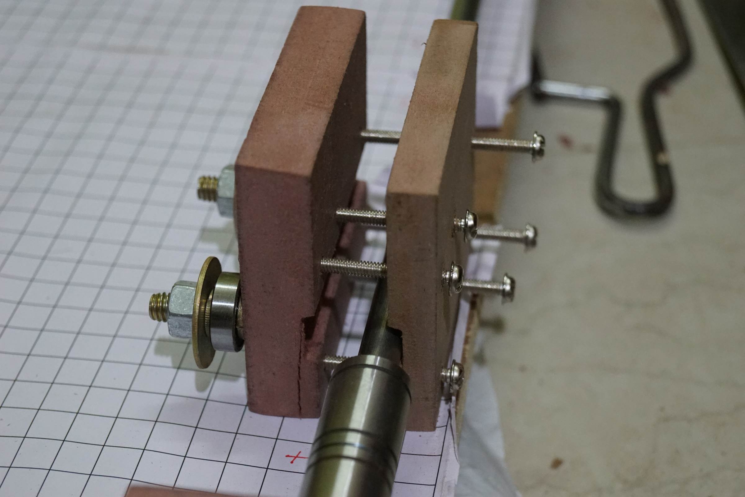
- X-Axis End Plates with a depression to support the LM10UU Linear Bearing of Y-Axis
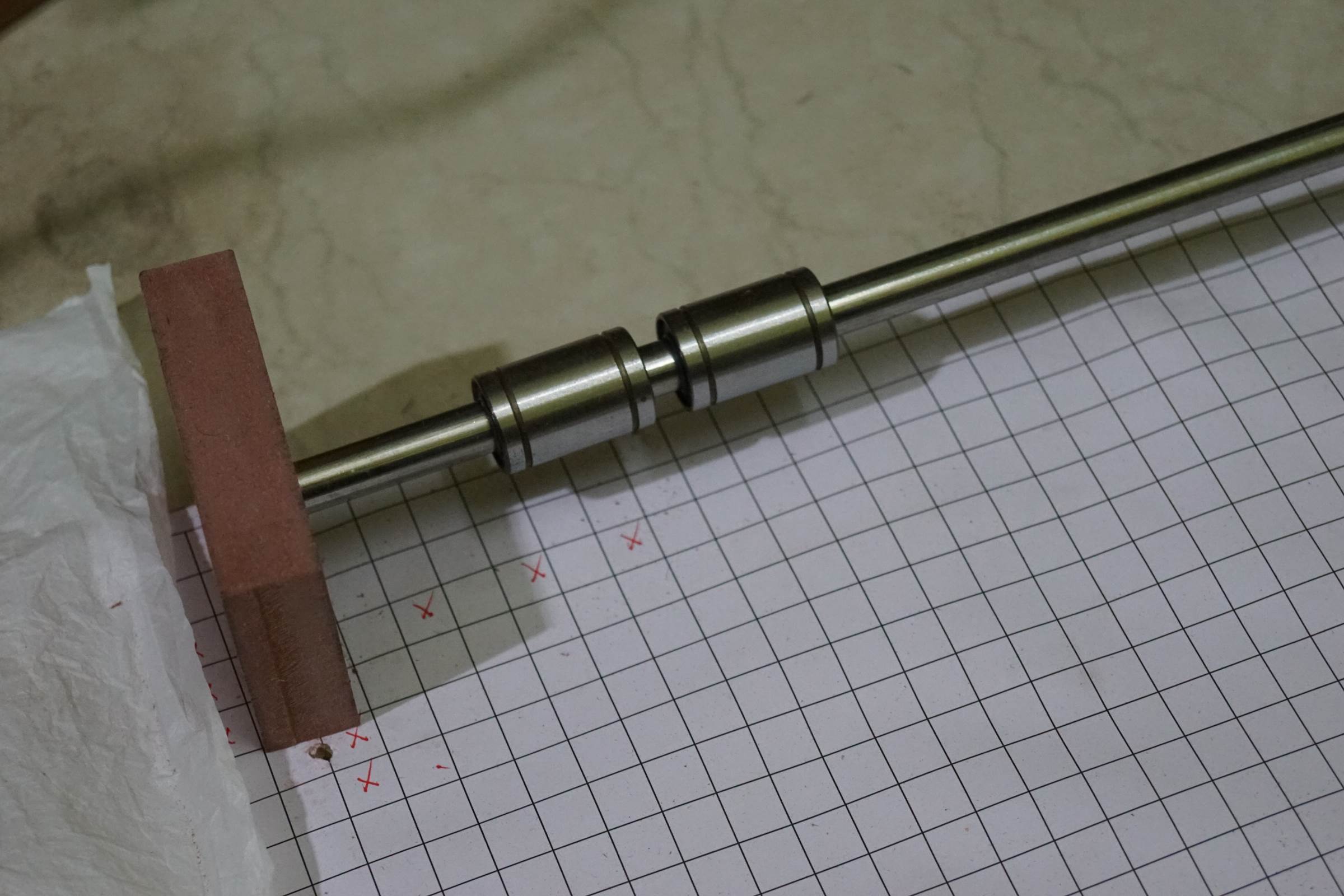
- X-Axis Center Carriage Plates with a depression to support the LM8UU Linear Bearing of X-Axis
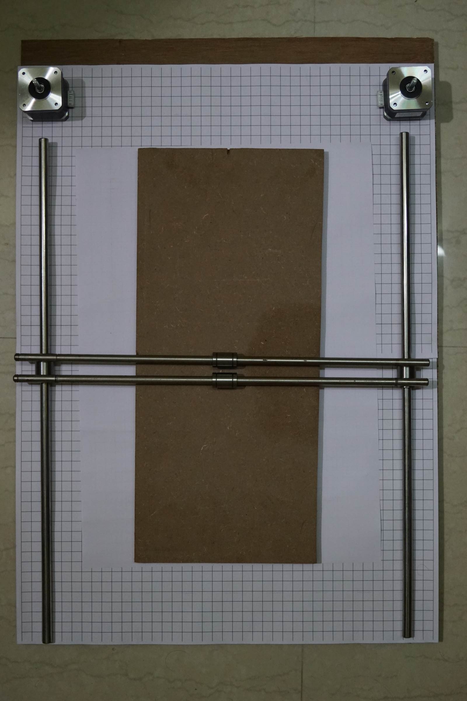
- Assembelled X-Axis of Arduino Drawing Machine, End Plates of the X-Axis were horizontal 8mm drilled to support two X-Axis rods
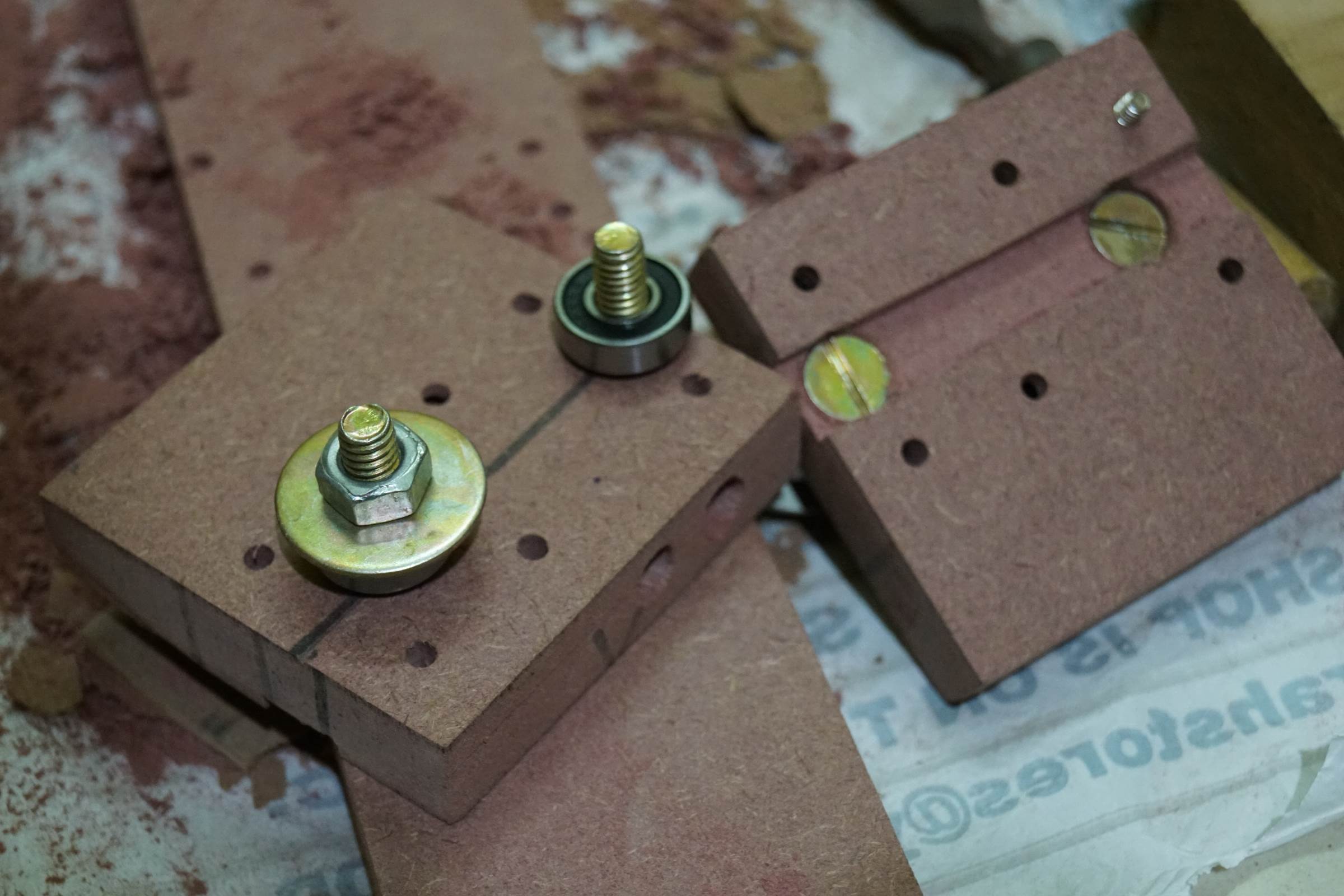
- Each X-Axis’ Upper-End Plates were drilled and bearings were attached on nut, bolt and washer to work like a pulley for the belt
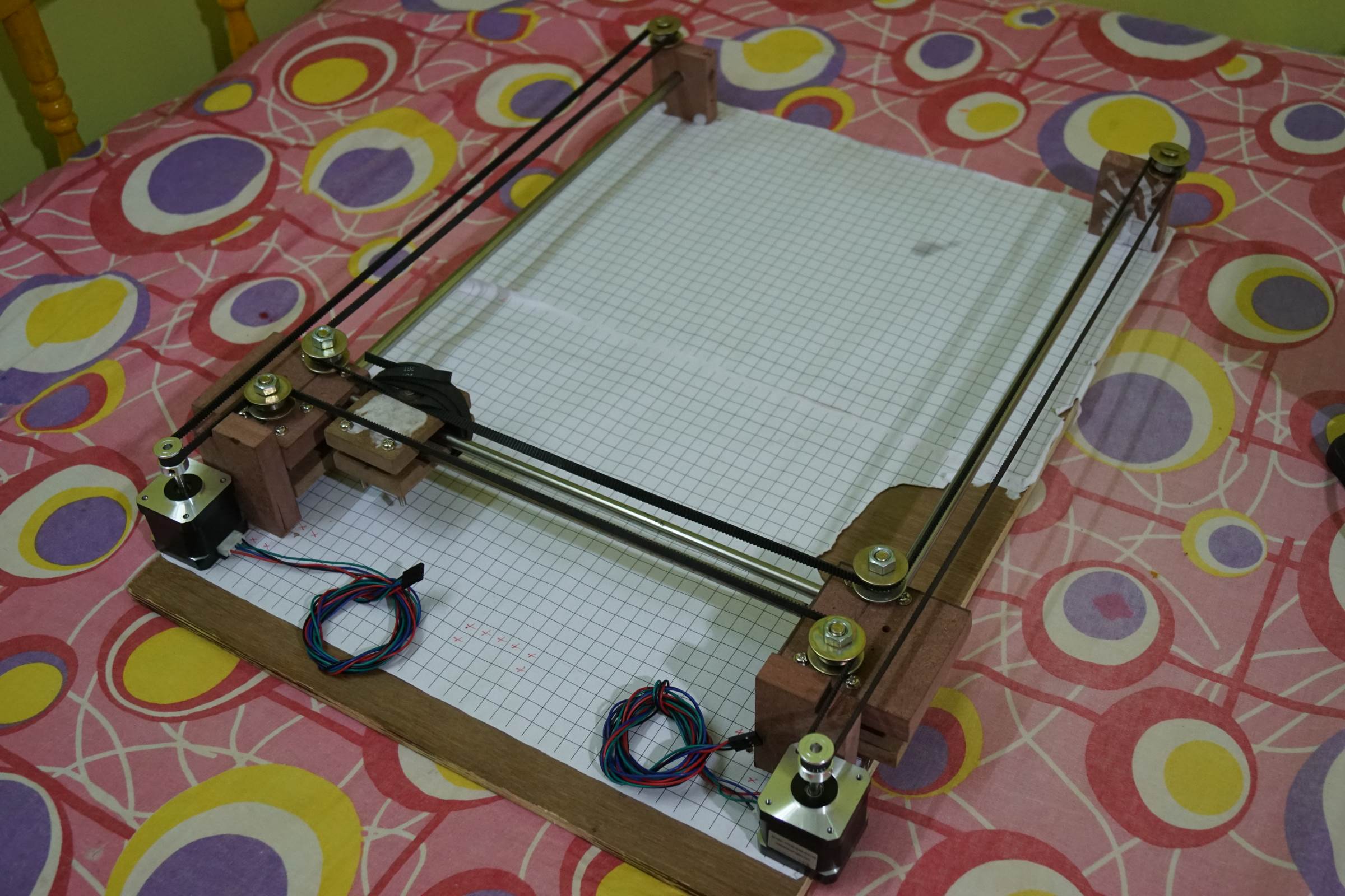
- Assembling the X Axis End Holders
- Assembling the X Axis End Holders
- Assembling the X Axis End Holders
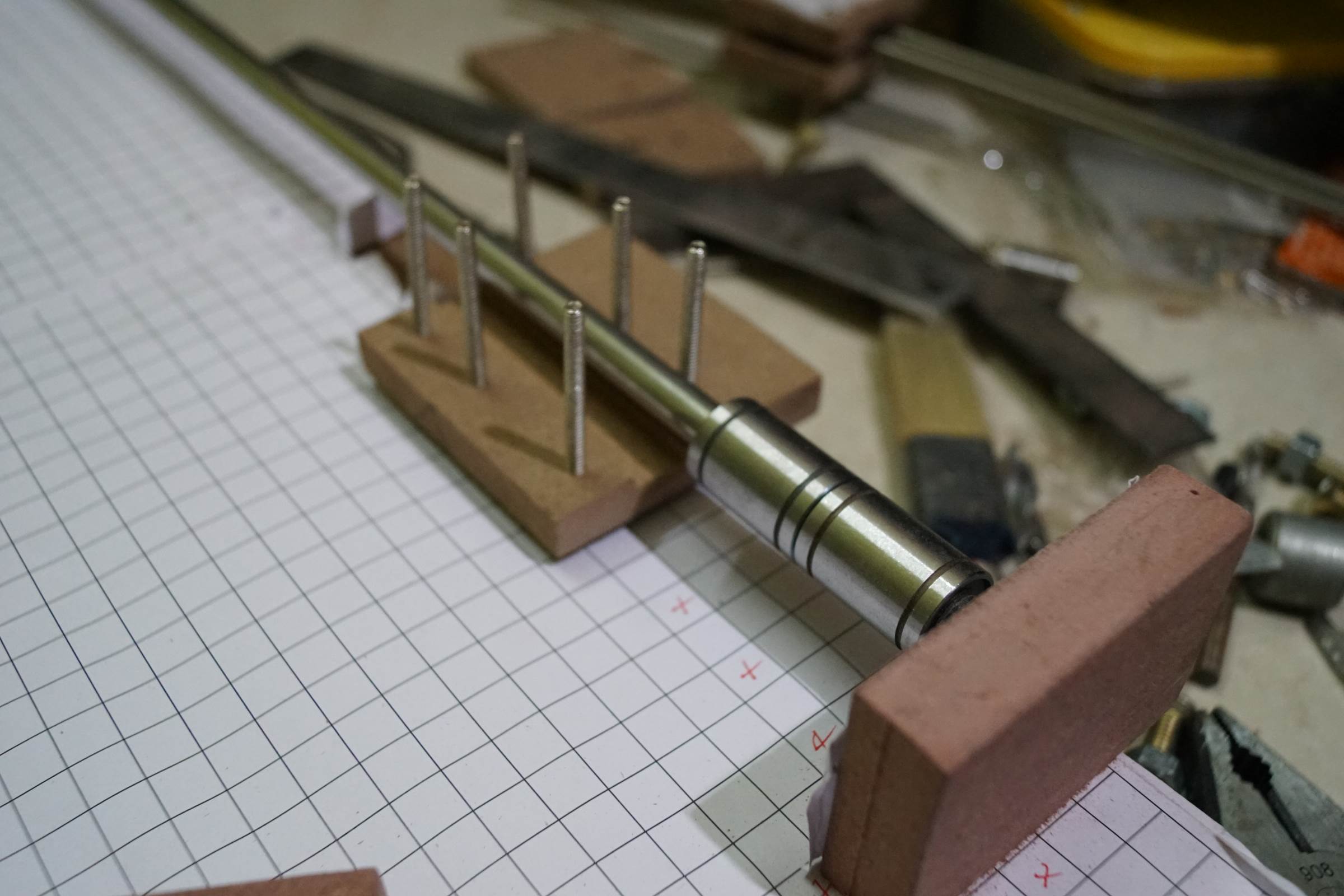
- Belt Assembly of Arduino Drawing Robot
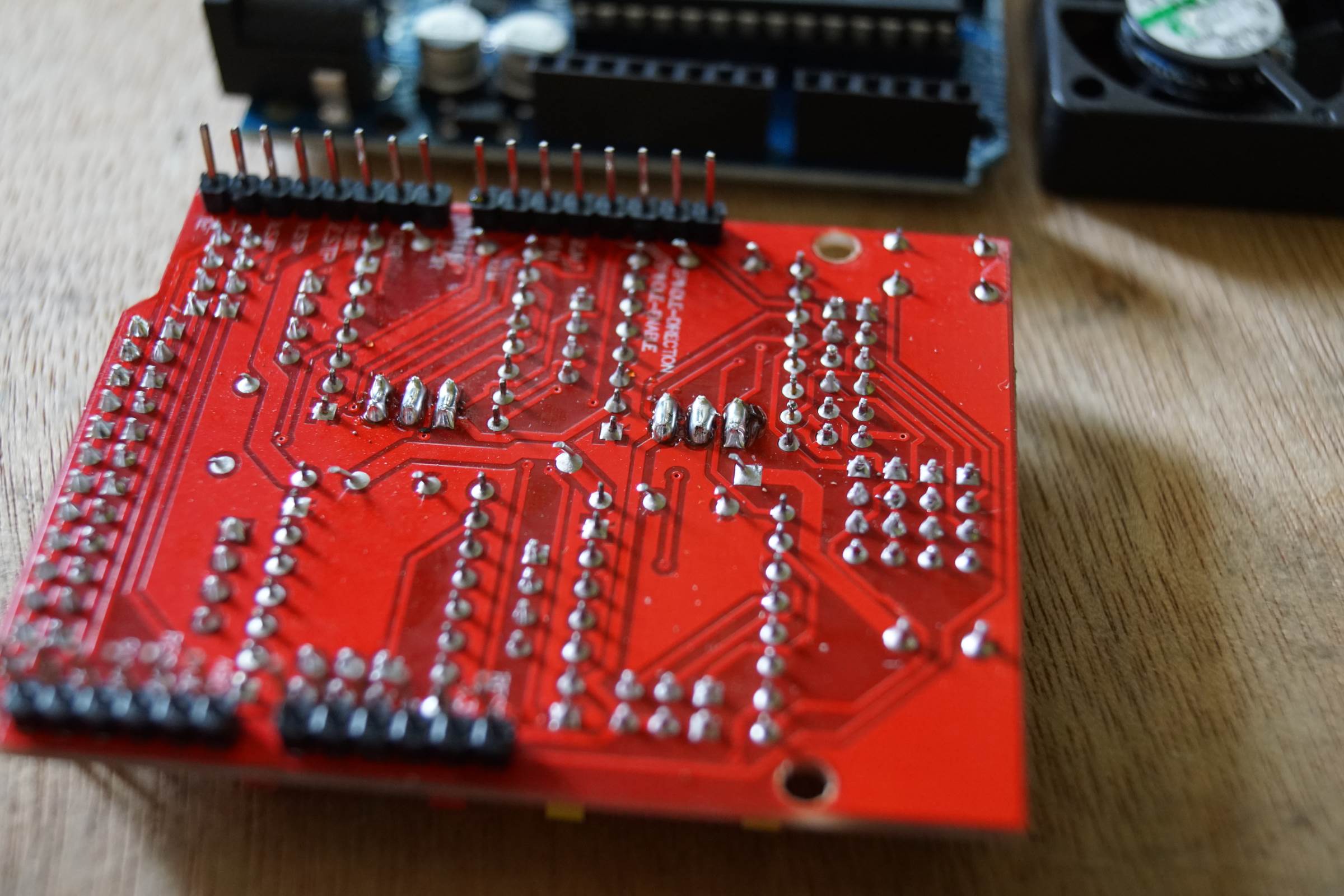
- Stepper Driver Micro Stepping Jumper Soldering for 1/32 Microstepping
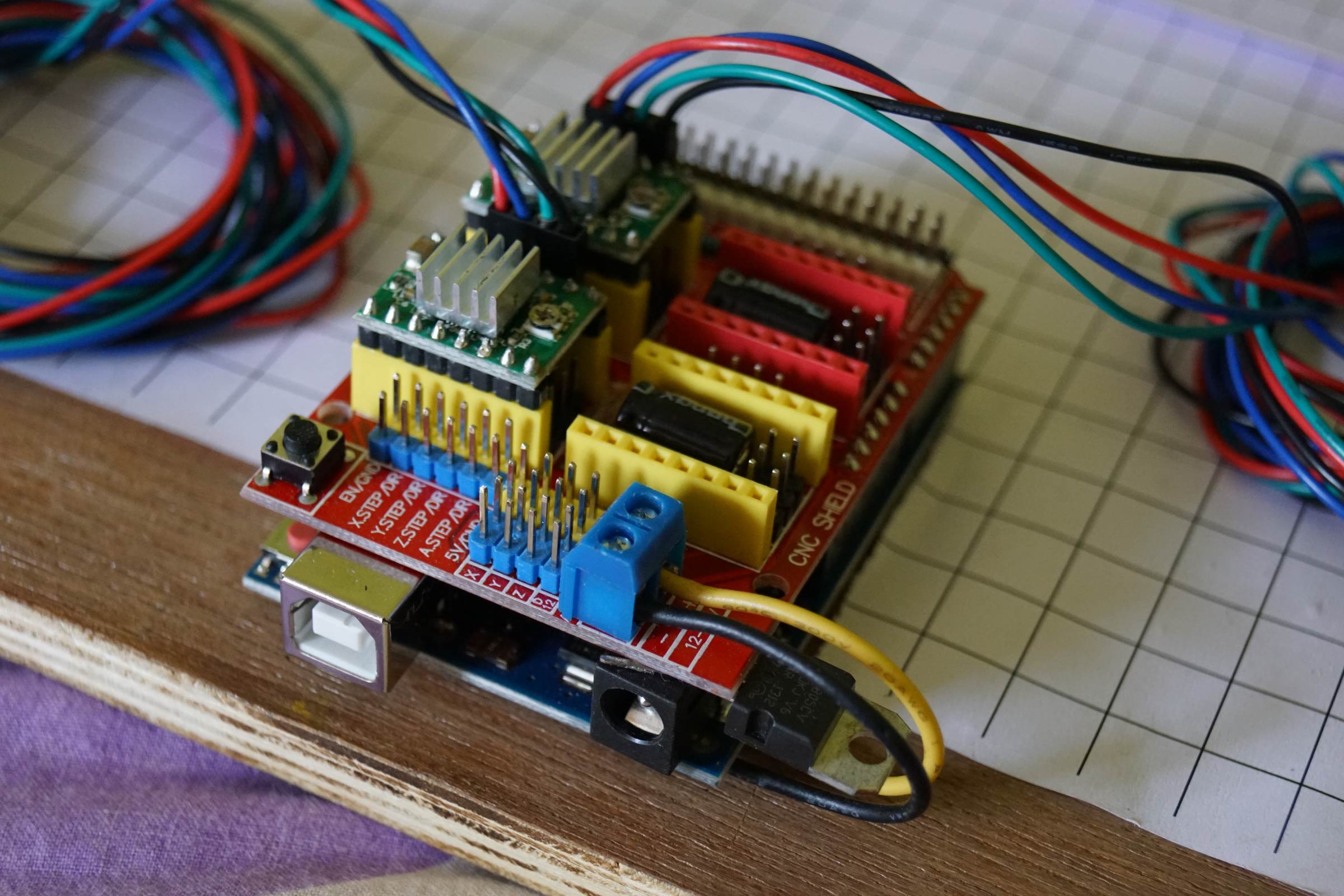
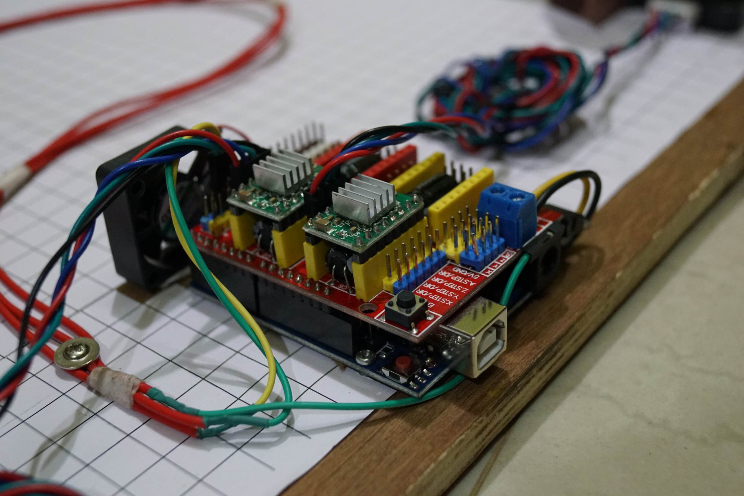
- A4988 Stepper Driver on CNC Shield V3, The Black and Yellow Wires Provides 12V from Arduino Uno ( Soldered on Bottom Side) to CNC Shield
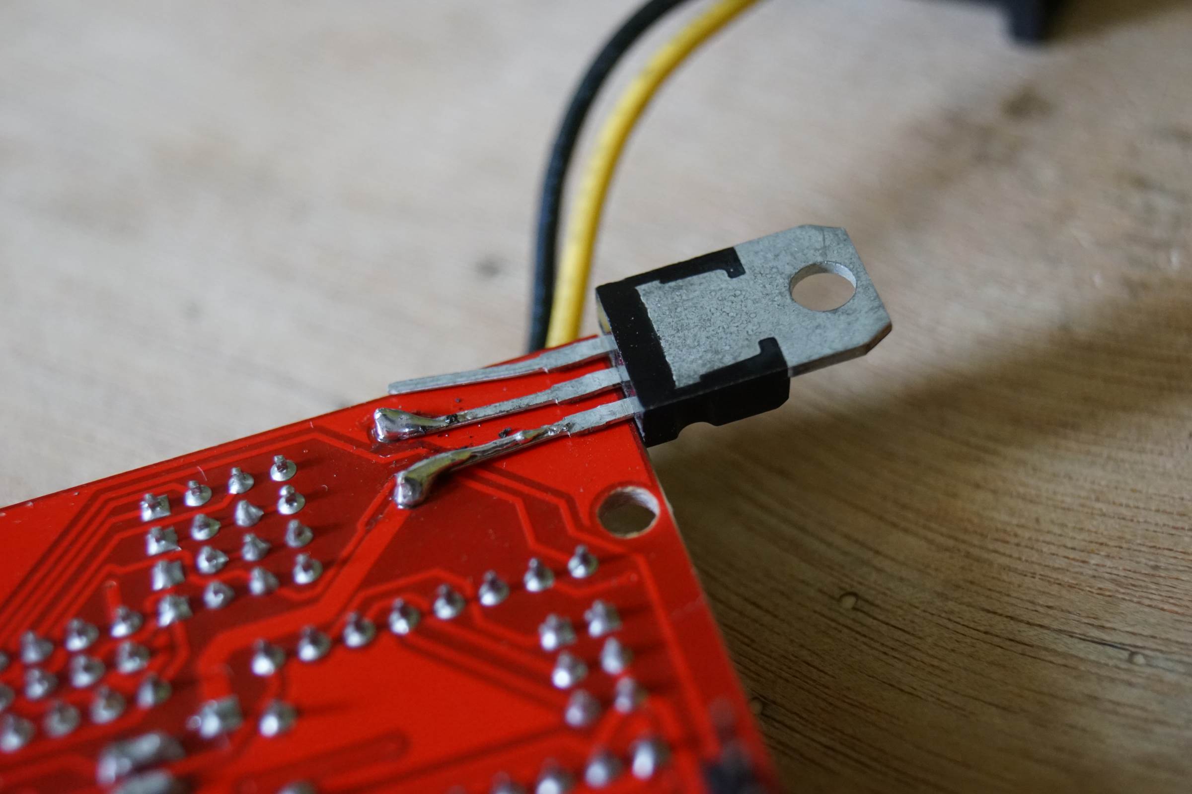
- LM7806 Soldered Directly on 12 Input to Provide 6V for Micro Servo
- Arduino CNC Drawing Machine Complete Wiring
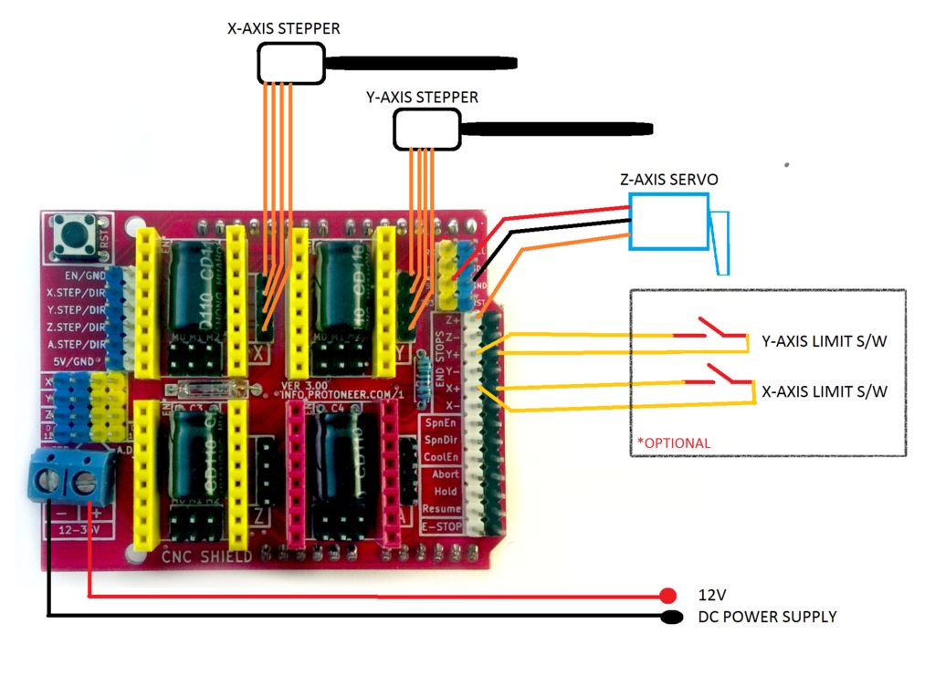
- Arduino Drawing Machine Schematics

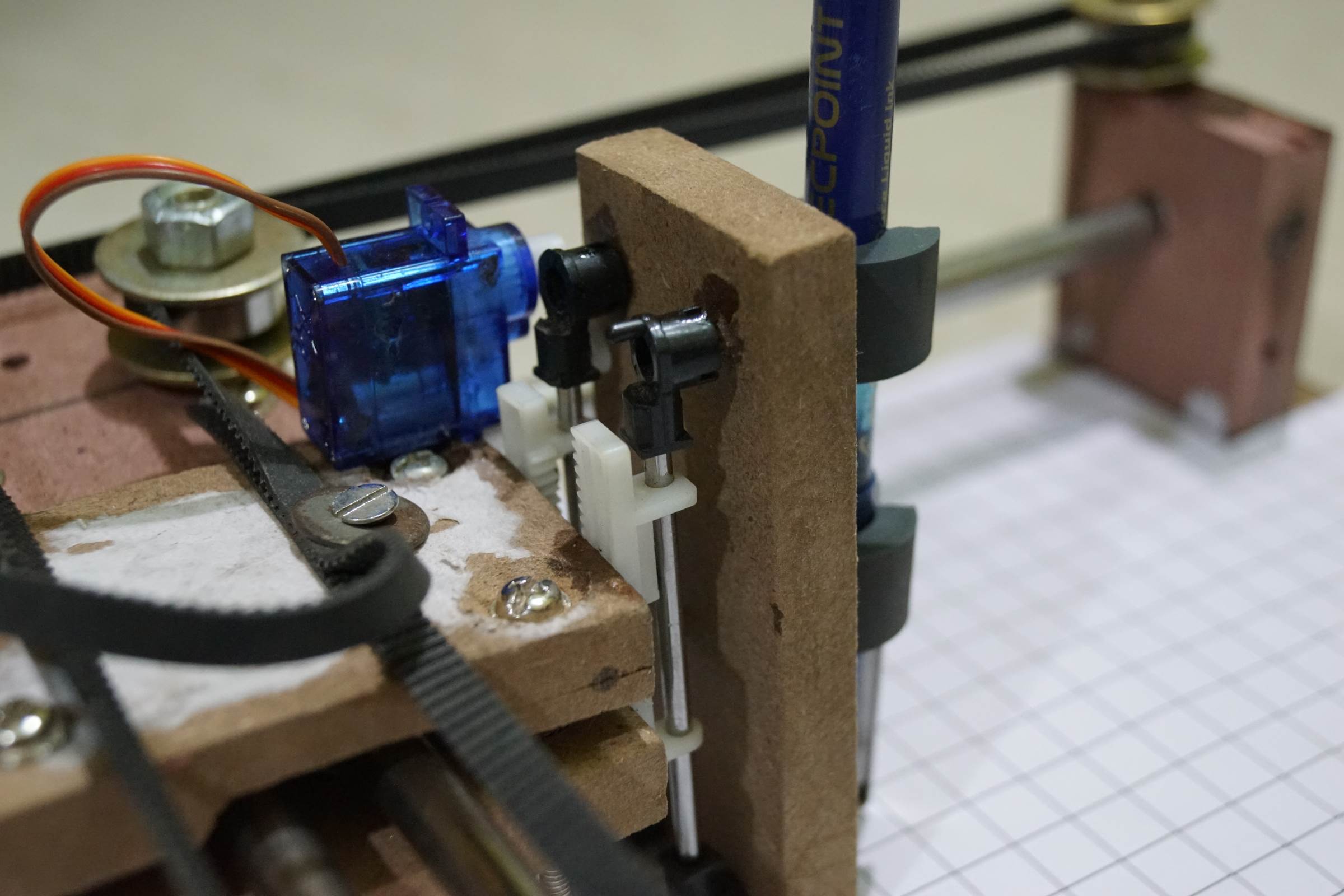
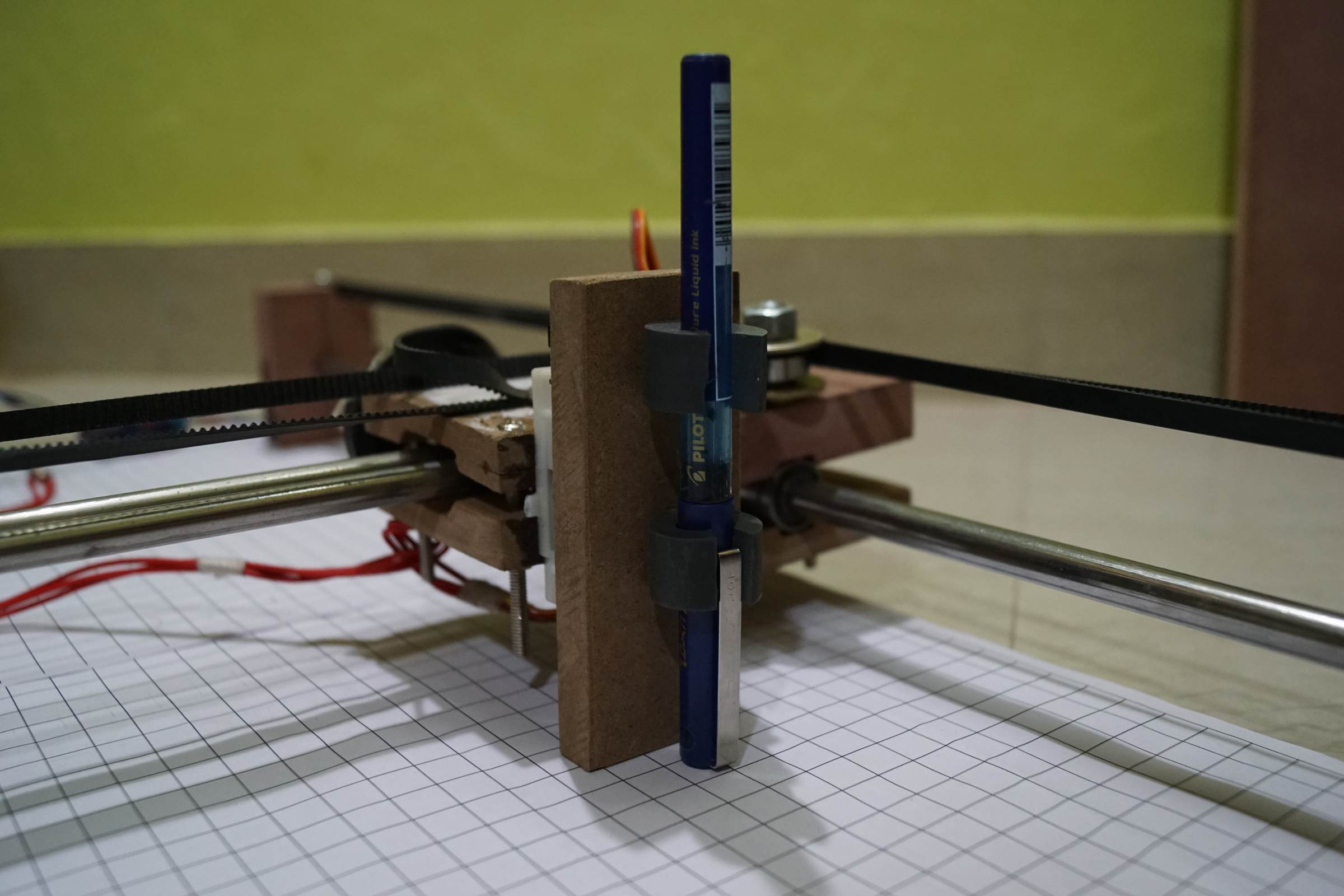
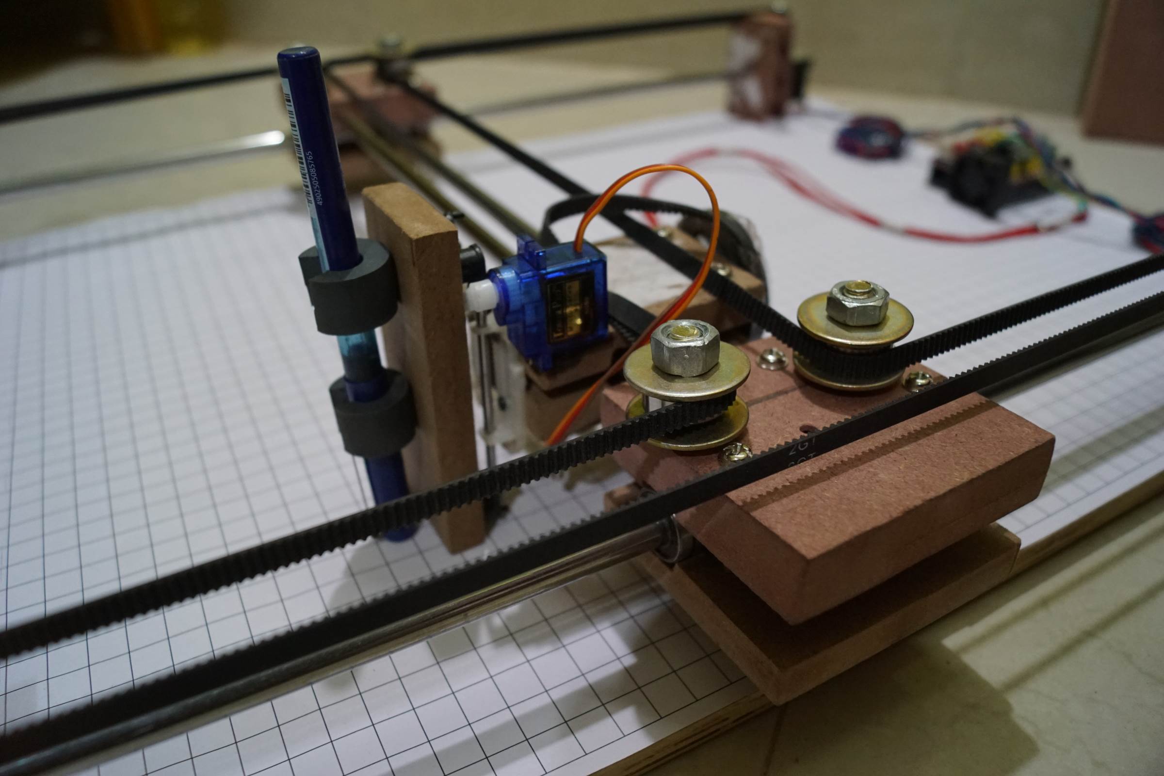
- Servo Motor Attachment for Pen Lifting in Arduino Drawing Machine
- Servo Motor Attachment for Pen Lifting in Arduino Drawing Machine
- Servo Motor Attachment for Pen Lifting in Arduino Drawing Machine
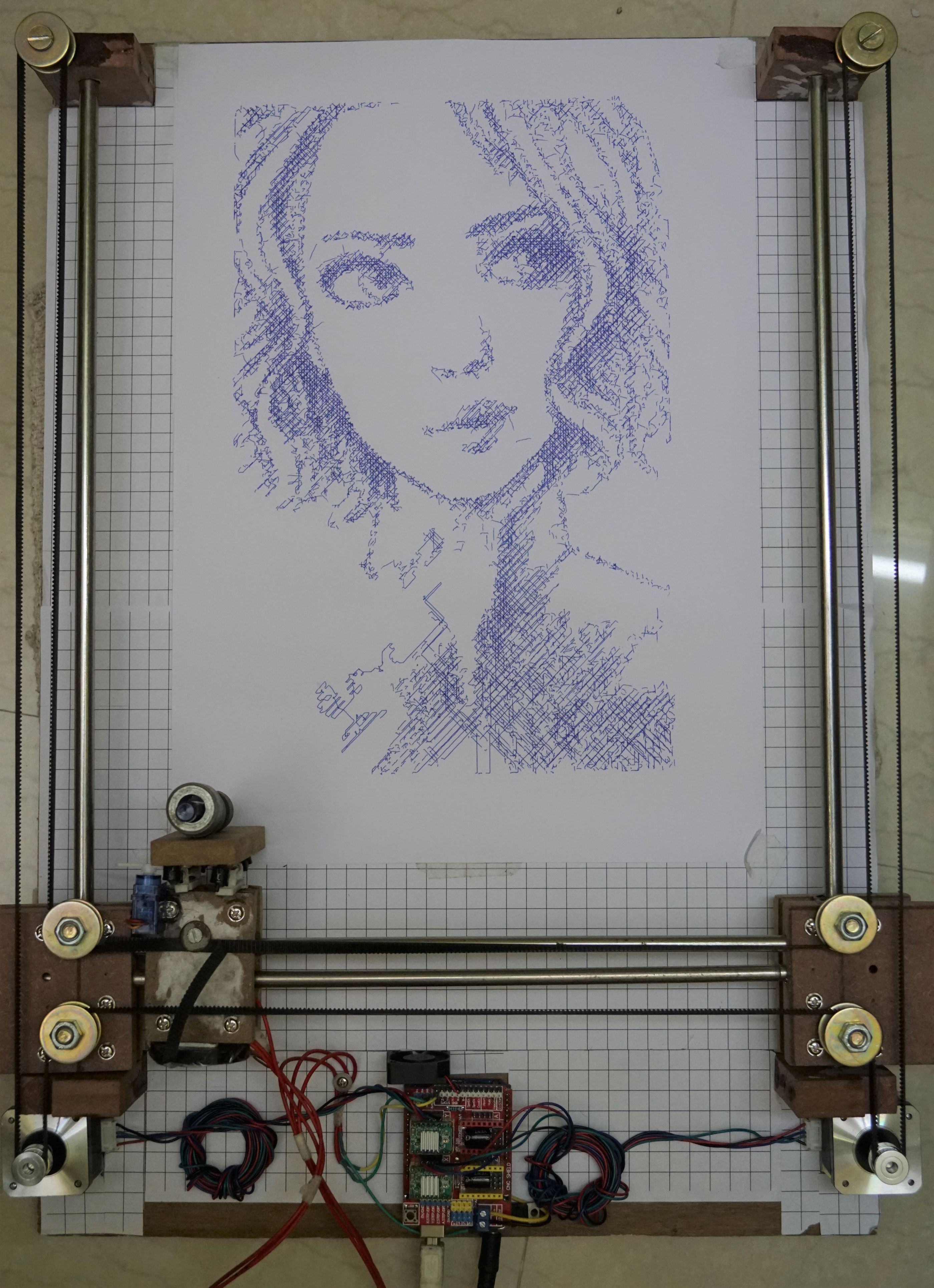
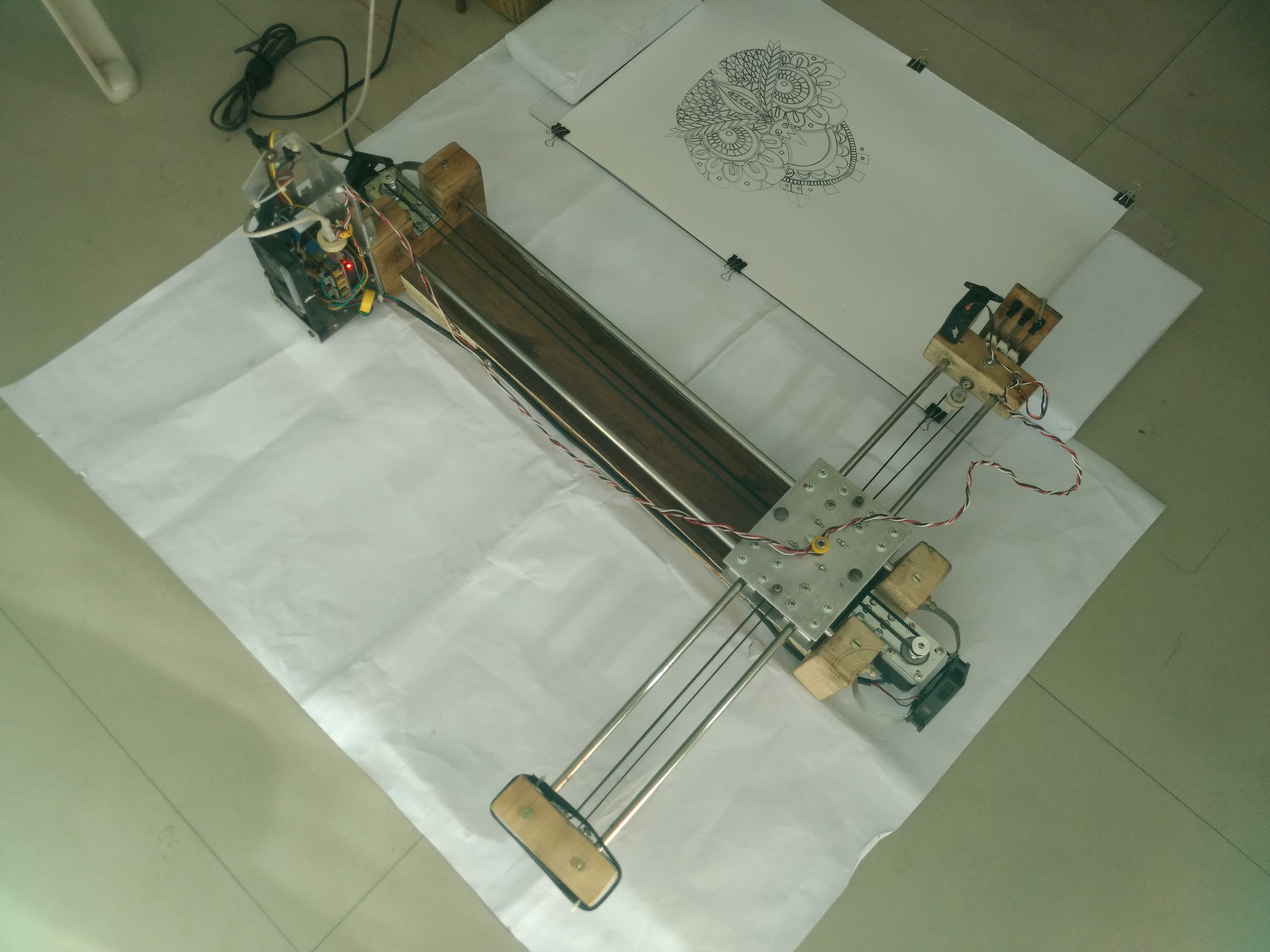
- Arduino Drawing Machine Working Output

- Arduino Drawing Machine Complete


Arduino Firmware Installation
This project is using a modified version of GRBL 0.9i Firmware that is. I have modified to enable CoreXY configuration and also enabled servo motor operation on pin D11. The servo motor will raise and lower the pen using Machine Code M03 and M05. (Will explain later in detail). So in Z-Axis, no Stepper Motor is required to pull the pen.
You Can Download my modified firmware from Git: https://github.com/arnabdasbwn/grbl-coreXY-servo
Grbl-coreXY-servo is a no-compromise, high performance, low-cost alternative to parallel-port-based motion control for CNC milling. It will run on a vanilla Arduino (Duemillanove/Uno) as long as it sports an Atmega 328p.
The controller is written in highly optimized C utilizing every clever feature of the AVR-chips to achieve precise timing and asynchronous operation. It is able to maintain up to 30kHz of stable, jitter-free control pulses.
It accepts standards-compliant G-Code and has been tested with the output of several CAM tools with no problems. Arcs, circles and helical motion are fully supported, as well as, all other primary G-Code commands. Macro functions, variables, and most canned cycles are not supported, but we think GUIs can do a much better job at translating them into straight G-Code anyhow.
Grbl-coreXY-servo includes full acceleration management with
• Licensing: Grbl is free software, released under the GPLv3 license.
After downloading you have to flash the Arduino Uno with the firmware.
Here are the Steps:
NOTE: Before starting, delete prior Grbl library installations from the Arduino IDE. Otherwise, you’ll have compiling issues! On a Mac, Arduino libraries are located in ~/Documents/Arduino/libraries/. On Windows, it’s in My Documents\Arduino\libraries.
1. Download from https://github.com/arnabdasbwn/grbl-coreXY-servo the ZIP File
• Unzip the download and you’ll have a folder called
2. Launch the Arduino IDE
• Make sure you are using the most recent version of the Arduino IDE!
3. Load Grbl into the Arduino IDE as a Library
• Click the Sketch drop-down menu, navigate to Include Library and select
• IMPORTANT: Select the Grbl folder inside the
• If you accidentally select the .zip file or the wrong folder, you will need to navigate to your Arduino library, delete the mistake, and re-do Step 3.
4. Open the GrblUpload Arduino example
• Click the File down-down menu, navigate to Examples->Grbl, and select GrblUpload.
5. Compile and upload Grbl-coreXY-servo to your Arduino
• Connect your Arduino Uno to your computer.
• Make sure your board is set to the Arduino Uno in the Tool->Board menu and the serial port is selected correctly in Tool->Serial Port.
• Click the Upload, and Grbl-coreXY-servo should compile and flash to your Arduino! (Flashing with a programmer also works by using the Upload Using Programmer menu command.)
Software Tools Installation
We need multiple software and plugins for generating art-work, editing and sending G-Code to the CNC using Serial COM Port. I will be discussing installation in Windows platform but you can find all the software for Linux platform too. So the software we will be using are:
>>> Inkscape
[ Will be used to edit vector graphics and also to generate vector graphics (.svg) from .jpg, .png and .dxf formats ]
• Download the latest stable 32bit/64bit version according to your OS from Inkscape.org
• Installation is pretty simple and straight forward in Windows. In Linux you need to type some easy commands.
• Just do a Next Next and software will be installed.
>>> JTP Laser Tool Inkscape Plugin
[This Inkscape plugin will convert paths/drawing to G-Code for Vector Printing]
• Download the plugin from JTP Website
• Extract it using any good unzipping software.
• Put the contents of this .zip folder into the “inkscape\share\extensions” folder in installationdirectory.
• Once it is there it will show up under the “extensions” tab in Inkscape.
>>> Raster 2 Laser G-Code Generator
[This Inkscape plugin will convert paths/drawing to G-Code for Raster Printing]
• Download the plugin from my Git Hub Repository Raster 2 Laser
• Extract it using any good unzipping software.
• Put the contents of this .zip folder into the “Inkscape\share\extensions” folder in installationdirectory.
• Once it is there it will show up under the “extensions” tab in Inkscape.
>>> UGS Platform / UniversalGcodeSender
[ Will send G-Codes from laptop to Arduino UNO via USB Serial Port]
• Download and install the version of Java listed on the download page according to your OS and system configuration. Requires Java 8. Download Here
• Download UGS Platform UGS Download
• Extract it using any good unzipping software.
• In the extracted folders locate bin in the ugsplatform directory.
• On Windows run ugsplatform.exe or ugsplatform64.exe, on Linux or Mac OSX run ugsplatform.
• No need of any installation or build.
>>> Camotics
[ Will be used for visualizing G-Codes and simulation purpose]
• Download the latest version from Camotics
• Simple and fluid installation.
>>> Makelangelo Software
[Will be used to generate monochrome pattern art work from jpg, png and other formats that can be printed by single colour pen by CNC Drawing Machine]
• Download the Makelangelo Software from my Git Hub Repository Makelangelo-Software
• Extract it using any good unzipping software.
• Open the extracted folder and find Makelangelo10.jar file.
• Run the .jar file using Java 8 you have installed in previous steps.
>>> Inkscape Template File
[This template will be used according to the paper feeded to the Drawing Machine and will help in G-Code generation with exact dimension]
• Download the template from my Git Hub Repository Inkscape-Template
• Extract it using any good unzipping software.
• Open the extracted folder and find Makelangelo10.jar file.
Processing from Existing JPG/PNG Image in Inkscape
• Open Inkscape.
• Open the template you have downloaded in previous step according to your paper size.
• Click on File -> Import then select the JPG or PNG file from your drive and click open.
• Resize and position the image according to your page size.
• Image must be inside the boundaries of the page or G-code will not be generated properly.
• Right Click on the image and select Trace Bitmap.
• Select any of the Three Option [ Experiment and You will know the working] Brightness Cutoff, Edge Detection, Colour Quantization.
• Change the threshold according to the details you want in the drawing.
• Click on Update.
• Click OK and close the window.
• The Vector Bitmap will be overlapping the original picture.
• Drag out the original picture and delete it. You are ready to generate G-code.
• Now See G-code Generation Step.
Processing from Custom Drawing in Inkscape
• Open Inkscape.
• Open the template you have downloaded in previous step according to your paper size.
• Start drawing or writing text inside the work area.
• Select all the objects by Ctrl+A shortcut.
• Group then together by Object -> Group from menu or by Ctrl+G shortcut.
• Then you have to convert object to path from menu Path -> Object To Path or by shortcut Shift+Ctrl+C. [ Important Step]
• Now See G-code Generation Step.
Generating Art Work from Image in Makelangelo Software
• Open Makelangelo Software running the .jar file.
• Click Open File and select the JPG/PNG file from your drive.
• Select the Conversion Style from the drop down menu. [ My fav is Crosshatch]
• Click ok.
• Click Save to file/SD Card and go to the location where you want to save.
• Put your file name and select DXF R12 File Format .DXF.
• Now run Inkscape and open the saved .DXF file with default settings.
• Resize it according to your need.
• Now See G-code Generation Step.
Raster G-code Generation
• In raster mode the machine will scan the whole drawing area from [0,0] till the end line by line. [Raster mode is slow and takes more time]. See the videos [Raster Drawing Girl’s Face Video 1] [Raster Drawing Girl’s Face Video 2]
• After converting all objects to path from previous step you are ready to generate your G-code.
• Now select all the paths that are inside the work area or use Ctrl+A.
• Click Extensions -> 305 Engineering -> Raster 2 Laser G-code Generator.
• Give Export Directory Path.
• Give File Name.
• Enable Numeric Suffix.
• Resolution means number of lines per mm, increasing will increase drawing time.
• Play with the options below like the RGB threshold.
• Set Engraving speed to 1500 or above.
• Select No Homing.
• Edit Laser ON to M03 S255.
• Edit Laser OFF to M05 S0.
• Deselect Preview, if selected no G-code will be generated.
• Click Apply. Wait and Enjoy. You are Ready to print now.
Vector G-code Generation
• In vector mode the machine will scan the only the drawing area where lines are there. [Vector mode drawing takes less time]. See the video [Vector Drawing PowerPuff Girls Video ]
• After converting all objects to path from previous step you are ready to generate your G-code.
• Now select all the paths that are inside the work area or use Ctrl+A.
• Click Extensions -> Generate laser G-code -> J Tech Photonics Laser Tool.
• Give Export Directory Path.
• Give File Name.
• Enable Numeric Suffix.
• Set All Units to mm.
• Set Laser speed to 1500 or above.
• Set Travel speed to 3000 or above.
• Select No Homing.
• Edit Laser ON to M03.
• Edit Laser OFF to M05.
• Deselect Preview
• Click Apply. Wait and Enjoy. You are ready to Print now.
GRBL Configuration and Setting Up Your Machine for the First Time
First, connect to Grbl using the serial terminal of your choice.
Set the baud rate to 115200 as 8-N-1 (8-bits, no parity, and
Once connected you should get the Grbl-prompt, which looks like this:
Grbl 0.9i [‘$’ for help]
Type $ and press enter to have Grbl print a help message. You should not see any local echo of the $ and enter. Grbl should respond with:
[HLP:$$ $# $G $I $N $x=val $Nx=line $J=line $SLP $C $X $H ~ ! ? ctrl-x]
The ‘$’-commands are Grbl system commands used to tweak the settings, view or change Grbl’s states and running modes, and start a homing cycle. The last four non-‘$’ commands are
$$ – View Grbl settings
To view the settings, type $$ and press enter after connecting to Grbl. Grbl should respond with a list of the current system settings, as shown in the example below. All of these settings are persistent and kept in EEPROM, so if you power down, these will be loaded back up the next time you power up your Arduino.
$x=val – Save Grbl setting
The $x=val command saves or alters a Grbl setting, which can be done manually by sending this command when connected to Grbl through a serial terminal program, but most Grbl GUIs will do this for you as a user-friendly feature.
To manually change e.g. the microseconds step pulse option to 10us you would type this, followed by an
$0=10
If everything went well, Grbl will respond with an ‘ok’ and this setting is stored in EEPROM and will be retained forever or until you change them. You can check if Grbl has received and stored your setting correctly by typing $$ to view the system settings again.
Grbl’s default configuration is intentionally very generic to help ensure users can see successful motion without having to tweak settings. Generally, the first thing you’ll want to do is get your stepper motors running, usually without it connected to the CNC. Wire Grbl to your stepper drivers and stepper motors according to your manufacturer guidelines. Connect to Grbl through a serial terminal or one of many Grbl GUIs. Send some G1 or G0 commands to Grbl. You should see your stepper motor rotating. If you are having trouble with your stepper motors, try the following:
• Ensure everything is wired and powered correctly per your stepper driver manufacturer guidelines.
• If your steppers are mounted in your CNC already, ensure your axes move freely and don’t obviously bind. If you can’t easily tell, try removing your steppers and check if they run under no load.
• Ensure your stepper motors and axes linear mechanisms are all tight and secure. Small set screws on drivetrain components becoming loose is a very common problem. Re-tighten and try applying some
• For more difficult issues, try the process of elimination to quickly isolate the problem. Start by disconnecting everything from the Arduino. Test if Grbl is operating ok by itself. Then, add one thing at a time and test.
• If your steppers are powered and making a grinding noise when trying to move, try lowering the ‘$’ acceleration and max rate settings. This sound is a sign that your steppers
• Grbl’s default step pulse settings cover the vast majority of stepper drivers on the market. While very uncommon, check these settings if you are still experiencing problems or have a
Next, you will need to make sure your machine is moving in the correct directions according to a Cartesian(XYZ) coordinate frame. Mount your stepper motors into your CNC, if you haven’t already done so. Send Grbl some motion commands, such as G91 G0 X1 or G91 G0 X-1, which will move the x-axis +1mm and -1mm, respectively. Check all axes. If an axis is not moving correctly, alter the $3 direction port mask setting to invert the direction.
If you are unfamiliar with how coordinate frames are
Finally, tune your settings to get close to your desired or max performance. Start by ensuring your $100,$101, and $102 axes step/mm settings are correct for your setup. This is dependent on your stepper increments, micro steps on your driver, and mechanical parameters. There are multiple resources online to show you how to compute this for your particular
At this point, you’re pretty much ready to get going! Grbl can now move your CNC machine and run G-code jobs. If you need to add more features, such as limit switches for homing or hard limits or spindle/laser control. There are other Wiki pages to help you that. Good luck and have fun!
Here is my GRBL Setting

$0 = 10 (step pulse, usec)
$1 = 25 (step idle delay, msec)
$2 = 0 (step port invert mask:00000000)
$3 = 0 (dir port invert mask:00000000)
$4 = 0 (step enable invert, bool)
$5 = 0 (limit pins invert, bool)
$6 = 0 (probe pin invert, bool)
$10 = 3 (status report mask:00000011)
$11 = 0.010 (junction deviation, mm)
$12 = 0.010 (arc tolerance, mm)
$13 = 0 (report inches, bool)
$20 = 0 (soft limits, bool)
$21 = 0 (hard limits, bool)
$22 = 0 (homing cycle, bool)
$23 = 0 (homing dir invert mask:00000000)
$24 = 25.000 (homing feed, mm/min)
$25 = 500.000 (homing seek, mm/min)
$26 = 250 (homing debounce, msec)
$27 = 1.000 (homing pull-off, mm)
$100 = 80.000 (x, step/mm)
$101 = 80.000 (y, step/mm)
$102 = 80.000 (z, step/mm)
$110 = 50000.000 (x max rate, mm/min)
$111 = 50000.000 (y max rate, mm/min)
$112 = 50000.000 (z max rate, mm/min)
$120 = 5000.000 (x accel, mm/sec^2)
$121 = 5000.000 (y accel, mm/sec^2)
$122 = 30.000 (z accel, mm/sec^2)
$130 = 310.000 (x max travel, mm)
$131 = 450.000 (y max travel, mm)
$132 = 200.000 (z max travel, mm)
Happy Making
Liking this content ? Please Donate to support this website ! 😇
141 Comments
Ghoni · July 12, 2021 at 2:17 am
Can I use UGS to setup machine in first time?
Crazy Engineer · July 13, 2021 at 12:39 am
Yes, You can use any tool to do the setup. You can use any Serial Monitor / Terminal.
Ghoni · July 13, 2021 at 8:34 am
ok thanks, but now have a problem to make g-code from inkscape. I use makelangelo software to make a dxf files. After that, i open that file with inkscape, select all and select object to path. Then i want to make raster gcode with raster to laser g-code generator extension. But, its take so long time. Can you tell me whats wrong with my steps?
Thankyou, and sorry for bad english
April Enaje · January 30, 2023 at 5:18 am
What Code did you use in this project?
chandan kumar · May 19, 2023 at 12:42 am
Can i make this for my B.tech final year project.
Theo Poyyayil · June 18, 2023 at 9:29 pm
Is it possible to buy one of this completed drawing board, if yes from where and what would be the price.
Many thanks and kind regards
Theo Poyyayil
Advait · November 18, 2024 at 7:13 pm
My servo(pen up and down) isn’t working. What is the problem? Im using SG90 servo