Introduction
This project is focused on designing and making a small project, 555 Timer LED Flasher. This is a basic electronics project that is fun to make and helps in learning electronics and designing methodology.
Prerequisite
For this project, it is good to have basic knowledge of PCB designing and soldering components. This is not a very difficult project to do. A basic understanding of electronics is also benefitial to identify components and correctly assemble them.
Hardware bill of materials
Below is the list of materials that I have used for the project. It is highly encouraged to buy them directly from the link below or add them to cart.
- Soldering Station / Soldering Iron
- Soldering Flux
- Soldering Wire
- PCB Helping Hands
- Multimeter
- SMD LED 1608 x 1
- 555 Timer IC x 1
- SMD Resistor x 3
- SMD Capacitor x 1
Software bill of materials
Hardware description
LM555
The LM555 is a highly stable device for generating accurate time delays or oscillation. Additional terminals are provided for triggering or resetting if desired. In the time delay mode of operation, the time is precisely controlled by one external resistor and capacitor. For astable operation as an oscillator, the free running frequency and duty cycle are accurately
controlled with two external resistors and one capacitor. The circuit may be triggered and reset on falling waveforms, and the output circuit can source or sink up to 200mA or drive TTL circuits.

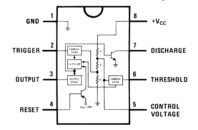
555 Timer IC Internal Schematic 
555 Timer IC Pin Out

Software description
KiCad
KiCad (pronounced “Key-CAD”) is a free software suite for electronic design automation (EDA). It facilitates the design of schematics for electronic circuits and their conversion to PCB designs. It features an integrated environment for schematic capture and PCB layout design and also has tools within the package to create a bill of materials, artwork, Gerber files, and 3D views of the PCB and its components.
Schematic Design
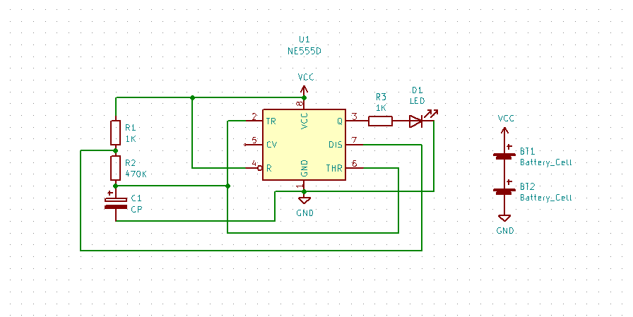
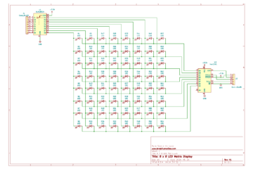
The below schematic is simple and doesn’t involve any complex circuitry. The schematic is designed in KiCad. The files are available for download at the end of the page.
This circuit uses the 555 timer in an Astable operating mode which generates a continuous output via Pin 3 in the form of a square wave. This turns the LED (D1) on and off. The speed at which the LED (D1) is turned on and off is set by the values of R1 and R2.
PCB Layout
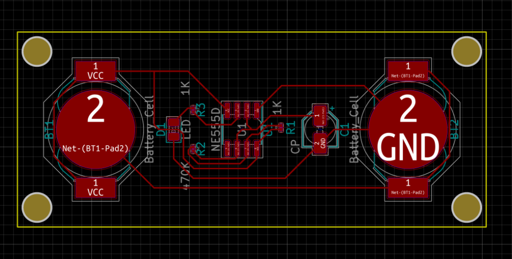
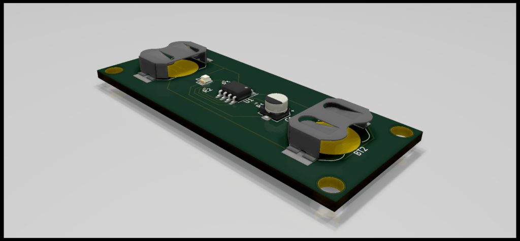
The PCB Layout is kept small and simple to accomodate two 12mm CR1220 Lithium 3V Battery, 555 Timer and other passive components. All the components are SMD to make it small and light.

PCB Layout of 555 Timer LED Flasher 
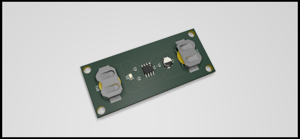
3D Render of 555 Timer LED Flasher 3D Render of 555 Timer LED Flasher
Conclusion
This particular project brings out learning about PCB design, component choices, cost of product, planning and many more. Best thing about this project is it encourages DIY and Maker culture which is an amazing thing by itself. I encourage everyone to do this project and make your own Modules and Boards for their projects.
Scope of Improvement
I have mentioned this project as v1.0 as there are so many things to improve in this project. One of the main improvements that can be done is to design the circuit with multiple LEDs.
Download
Thanks for reading this project, I highly appreciate your time and effort.
0 Comments