Introduction
This project is focused on designing and making our own Reflectance Sensor Array that is similar to Pololu QTR-8RC or Parallex QTI Sensor which can be used for Line Follower Robots. This project is compatible with many microcontroller or microprocesor with 5V Logic. MCUs with 3.3V Logic needs Logic Converter. The project uses Vishay Semiconductors’ Optical Reflex Sensors CNY70 which is a THT component but it is very small and keeps a small form factor for the module. This is compatable with all Arduino Boards. This Reflectance Sensor Array module is designed with 10 Reflex Sensors which increases resolution as most sensor modules in market are just 8 IR LED / Phototransistor pairs.
Prerequisite
For this project, it is good to have basic knowledge of PCB designing and soldering components. This is not a very difficult project to do. A basic understanding of electronics is also benefitial to identify components and correctly assemble them.
Hardware bill of materials
Below is the list of materials that I have used for the project. It is highly encouraged to buy them directly from the link below or add them to cart.
- Soldering Station / Soldering Iron
- Soldering Flux
- Soldering Wire
- PCB Helping Hands
- Multimeter
- 0.1uf Capacitor x 10
- 220Ω Resistor x 1
- 470Ω Resistor x 1
- CNY70 Reflex Sensor x 10
- Male 2.54mm Header Connector x 1
Software bill of materials
Hardware description
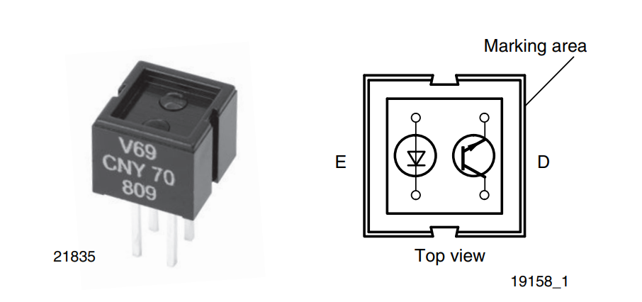
CNY70
The CNY70 is a Vishay Semiconductors’ Optical Reflective Sensor that includes an infrared emitter and phototransistor in a leaded package which blocks visible light.
The operating principles of reflex sensors are similar to those of transmissive sensors. Basically, the light emitted by the transmitter is influenced by an object or a medium on its way to the detector. The change in the light signal caused by the interaction with the object then produces a change in the electrical signal in the optoelectronic receiver. The main difference between reflex couplers and transmissive sensors is in the relative position of the transmitter and detector with respect to each other. In the case of the transmissive sensor, the receiver is opposite the transmitter in the same optical axis, giving a direct light coupling between the two. In the case of the reflex sensor, the detector is positioned next to the transmitter, avoiding a direct light coupling.
The reflex sensor CNY70 contain IR-emitting diodes as transmitters and
phototransistors as receivers. The transmitters emit radiation of a wavelength of 950 nm. The spectral sensitivity of the phototransistors are optimized at this wavelength.

CNY70 Reflectance Sensor Block Diagram 
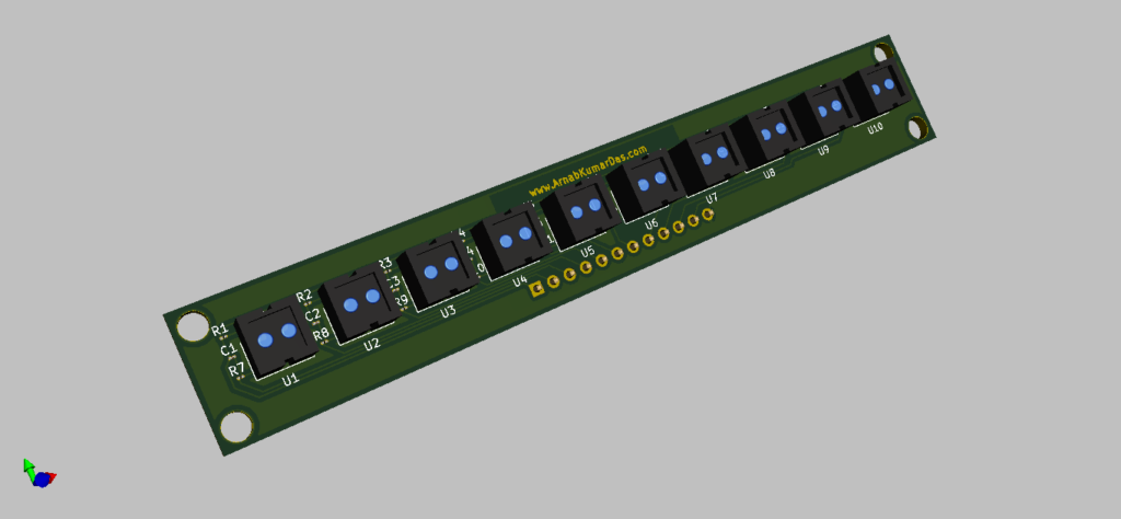
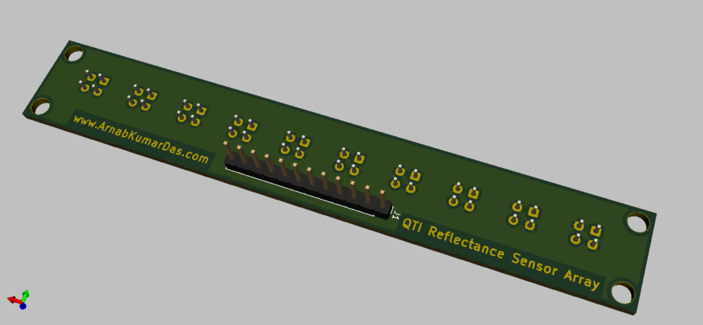
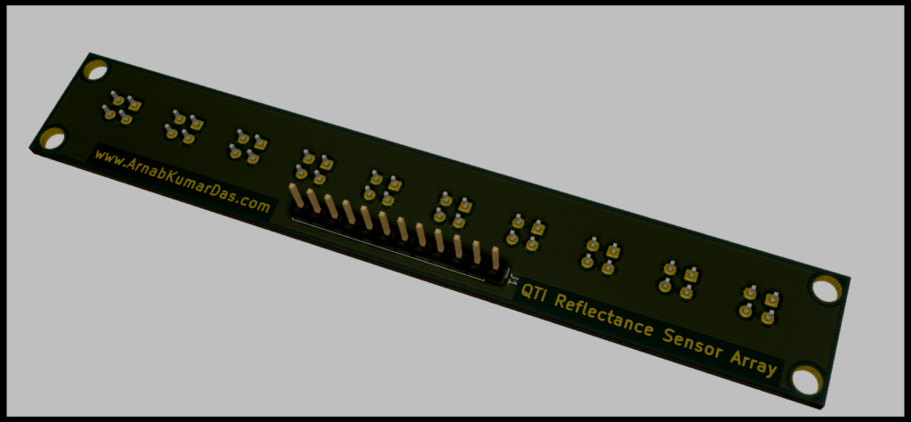
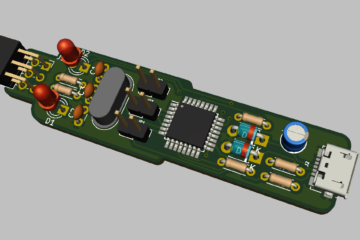
3D Render of Reflectance Sensor Array for Line Follower Robot PCB 3D Render of Reflectance Sensor Array for Line Follower Robot PCB
Software description
KiCad
KiCad (pronounced “Key-CAD”) is a free software suite for electronic design automation (EDA). It facilitates the design of schematics for electronic circuits and their conversion to PCB designs. It features an integrated environment for schematic capture and PCB layout design and also has tools within the package to create a bill of materials, artwork, Gerber files, and 3D views of the PCB and its components.
Schematic Design
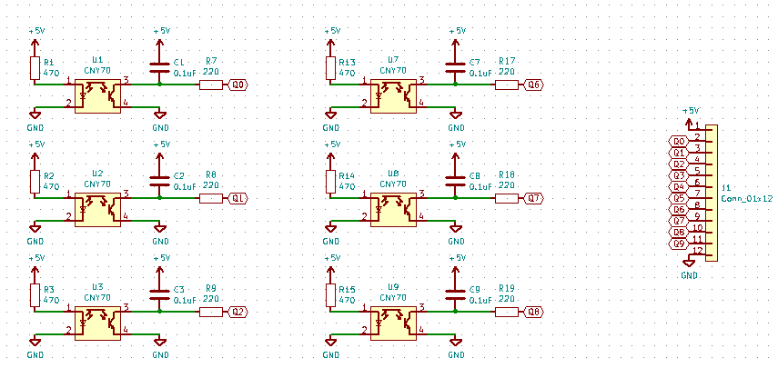
The below schematic is simple and doesn’t involve any complex circuitry. The schematic is designed in KiCad. The files are available for download at the end of the page.
The major components of the Reflectance Sensor Array design is the CNY70 Reflex Sensor.
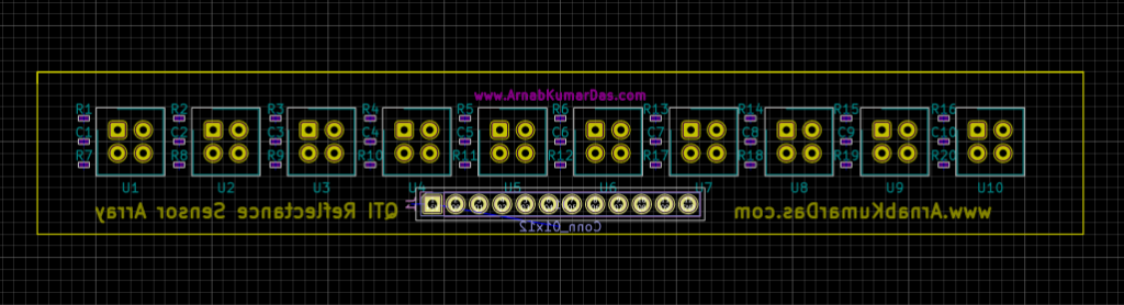
PCB Layout
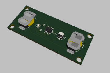
The PCB Layout is completely designed in KiCad. A 3D view / render of the PCB is also available in KiCad. The USBasp programmer is designed to improve usability, reduce footprint and aesthetics.

Reflectance Sensor Array for Line Follower Robot PCB Layout Raytrace 3D Render of Reflectance Sensor Array for Line Follower Robot PCB Raytrace 3D Render of Reflectance Sensor Array for Line Follower Robot PCB Raytrace 3D Render of Reflectance Sensor Array for Line Follower Robot PCB


Conclusion
This particular project brings out learning about PCB design, component choices, cost of product, planning and many more. Best thing about this project is it encourages DIY and Maker culture which is an amazing thing by itself. I encourage everyone to do this project and make your own Modules and Boards for their projects.
Scope of Improvement
I have mentioned this project as v1.0 as there are so many things to improve in this project. One of the main improvements that can be done is to use all SMD Connectors to further reduce the formfactor etc.
Download
Thanks for reading this project, I highly appreciate your time and effort.
1 Comment
Mrs. RUSHALI · August 15, 2020 at 8:25 pm
good job needs to talk with you mob no 9158126777