Introduction
This project is focused on designing and making our own 8 x 8 LED Matrix Display. I have shared many PCB designs in this website. In this project I want you to design the PCB Layout. To make things easy I have already designed the Schematic of 8 x 8 LED Matrix Display.
Prerequisite
For this project, it is good to have basic knowledge of PCB designing and soldering components. This is not a very difficult project to do. A basic understanding of electronics is also benefitial to identify components and correctly assemble them.
Hardware bill of materials
Below is the list of materials that I have used for the project. It is highly encouraged to buy them directly from the link below or add them to cart.
- Soldering Station / Soldering Iron
- Soldering Flux
- Soldering Wire
- PCB Helping Hands
- Multimeter
- SMD LED 1608 x 64
- ULN2803 x 1
- 74HC595 x 1
- Male 2.54mm Header Connector x 1
Software bill of materials
Hardware description
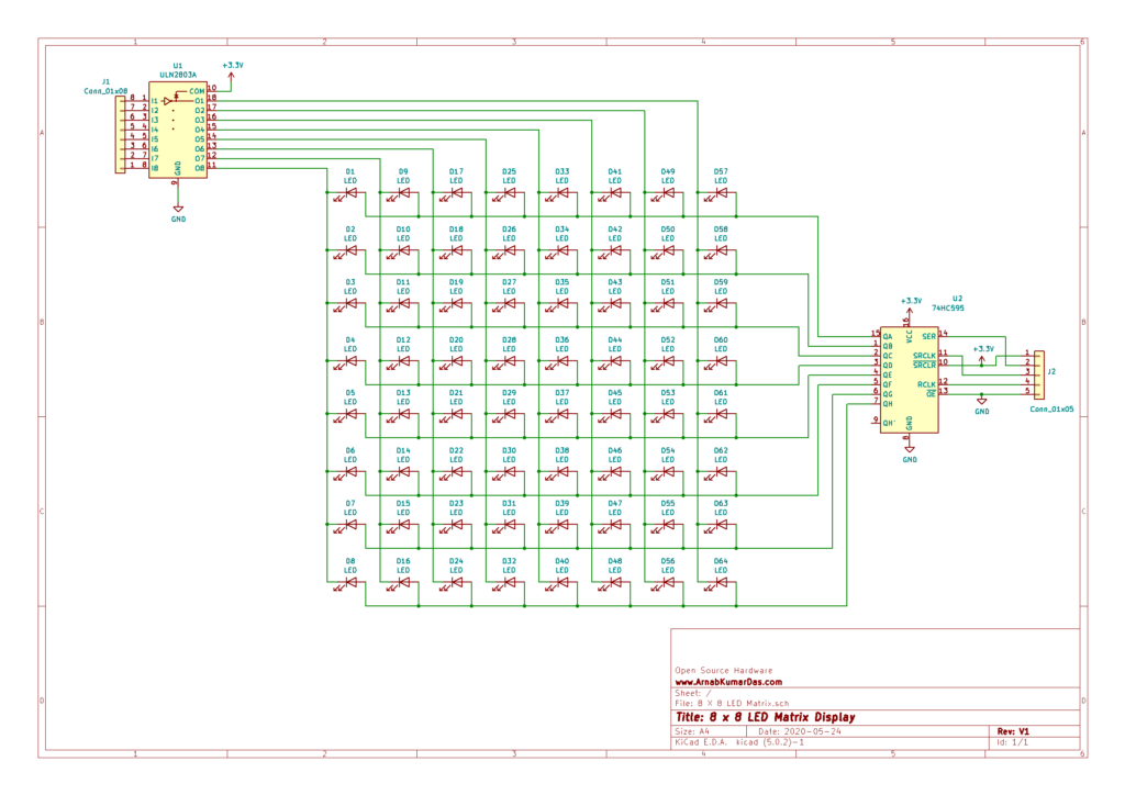
ULN2803A
The ULN2803A device is a 50 V, 500 mA Darlington transistor array. The device consists of eight NPN Darlington pairs that feature high-voltage outputs with common-cathode clamp diodes for switching inductive loads. The collector-current rating of each Darlington pair is 500 mA. The Darlington pairs may be connected in parallel for higher current capability.
Applications include relay drivers, hammer drivers, lamp drivers, display drivers (LED and gas discharge), line drivers, and logic buffers. The
ULN2803A device has a 2.7-kΩ series base resistor for each Darlington pair for operation directly with TTL or 5-V CMOS devices.
74HC595
The HC595 devices contain an 8-bit serial-in, parallel-out shift register that feeds an 8-bit D-type storage register. The storage register has parallel
3-state outputs. Separate clocks are provided for both the shift and storage register. The shift register has a direct overriding clear (SRCLR) input, serial (SER) input, and serial outputs for cascading. When the output-enable (OE) input is high, the outputs are in the high-impedance state. Both the shift register clock (SRCLK) and storage register clock (RCLK) are positive-edge triggered. If both clocks are connected together, the shift register always is one clock pulse ahead of the storage register.
Software description
KiCad
KiCad (pronounced “Key-CAD”) is a free software suite for electronic design automation (EDA). It facilitates the design of schematics for electronic circuits and their conversion to PCB designs. It features an integrated environment for schematic capture and PCB layout design and also has tools within the package to create a bill of materials, artwork, Gerber files, and 3D views of the PCB and its components.
Schematic Design
The below schematic is simple and doesn’t involve any complex circuitry. The schematic is designed in KiCad. The files are available for download at the end of the page.
PCB Layout
The PCB Layout is not shared for the project. Other files are shared to help you with the project.
Conclusion
This particular project brings out learning about PCB design, component choices, cost of product, planning and many more. Best thing about this project is it encourages DIY and Maker culture which is an amazing thing by itself. I encourage everyone to do this project and make your own Modules and Boards for their projects.
Scope of Improvement
I have mentioned this project as v1.0 as there are so many things to improve in this project. One of the main improvements that can be done is to design the circuit so that it can be cascaded to make big LED Matrix Displays.
Download
Thanks for reading this project, I highly appreciate your time and effort.
1 Comment
Vimal · October 12, 2020 at 9:36 pm
8 X 8 LED Matrix.zip file can be use as a greber file