Note
This article is a part of Arduino / ATmega328p Embedded C Firmware Programming Tutorial. Consider exploring the course home page for articles on similar topics.

Arduino Tutorial Embedded C Register Level Arduino Master Class
Also visit the Release Page for Register Level Embedded C Hardware Abstraction Library and Code for AVR.
Introduction
The I2C (Inter-Integrated Circuit) is a half-duplex, synchronous serial communication interface specification used for short-distance communication, primarily in embedded systems. The interface was developed in 1982 by Philips Semiconductor (now NXP Semiconductors). The I²C communication is a master-slave protocol with a single or many master devices and one or more slave devices. I2C (Inter-Integrated Circuit) is used for communicating with microcontrollers, microprocessors, LCDs, sensors (Gyroscope, etc.), memory devices (Flash, EEPROM) and is widely used in modern-day embedded hardware.
I2C is spelled I2C (pronounced I-two-C) or IIC (pronounced I-I-C).
What You Will Learn
- How does I2C communication work in Arduino?
- How does I2C communication work in AVR ATmega328p?
- What are the Pros and Cons of I2C communication?
- What is the I2C Data Frame format?
I²C Features
- Half duplex communication
- Multi master – multi slave architecture [Usually single master]
- Low speed communication [Usually kHz, Rarely MHz]
- Open-drain / open-collector with an input buffer on the same line, which allows a single data line to be used for bidirectional data flow
- Each signal line has a pull-up resistor on it, to restore the signal to HIGH when no device is asserting it low
- Each device on the bus has unique address and is software addressable
- Two wire / pin serial bus
- Serial Data Line (SDA) – Carries data to and fro from master and slave devices
- Serial Clock Line (SCL) – Clock driven by the master device to slave device, used to synchronize the data bits
- Short distance communication, usually on the same PCB / system
| Term | Description |
|---|---|
| Master | The device that initiates and terminates a transmission. The master also generates the SCL clock |
| Slave | The device addressed by a master |
| Transmitter | The device placing data on the bus |
| Receiver | The device reading data from the bus |
I²C Bus Electrical Characteristics
I²C bus uses two wires/pins to communicate between devices. The two wires/pins are SDA and SCL. Data flows in and out through the SDA pin. The SCL pin is used to synchronize the data transfer by supplying a clock signal. In an I²C bus architecture, different peripherals may share a bus that is connected to a processor through only 2 wires. I²C uses either 7 bit or 10 bit addressing mode. In 7 bit mode, it supports 128 devices on the bus, and in 10 bit mode, it supports 1008 devices on the bus.
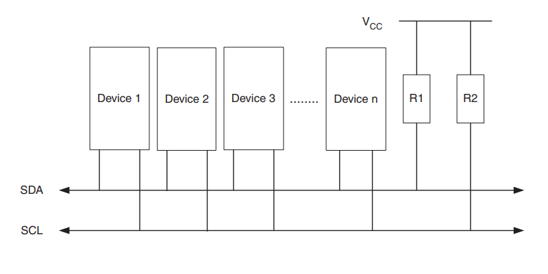
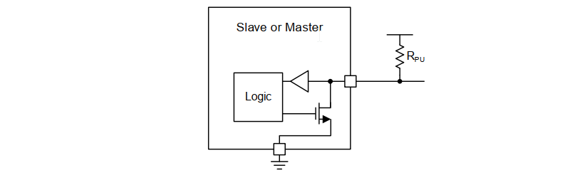
I2C uses an open-drain / open-collector with an input buffer on the same line. This allows a single data line to be used for bidirectional data flow.
In an open-drain configuration, by default, the bus lines are pulled up to power rail / VCC / logic HIGH by pull-up resistors (R1 / R2 / RPU) the device can only pull the bus line down by connecting it to ground/logic LOW. The devices usually implement this using a FET or transistor in a switch configuration. In the event of the bus being released by the master or a slave, the pull-up resistor (R1 / R2 / RPU) on the line is responsible for pulling the bus voltage up to the power rail. This prevents any communication clashes or short circuit between power and ground.
The size of the pull-up resistor is determined by the amount of capacitance on the I2C lines. In most cases, 4.7k resistors are used. The bus is only limited by the bus capacitance limit of 400 pF.
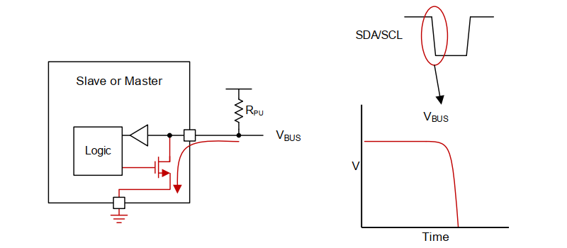
When a logic LOW needs to be transmitted the I2C hardware activates the pull-down FET to connect the bus line to GND. A small current flows from power to ground via a pull-up resistor (RPU) and voltage on the bus line equals to ground which will be interpreted as LOW.
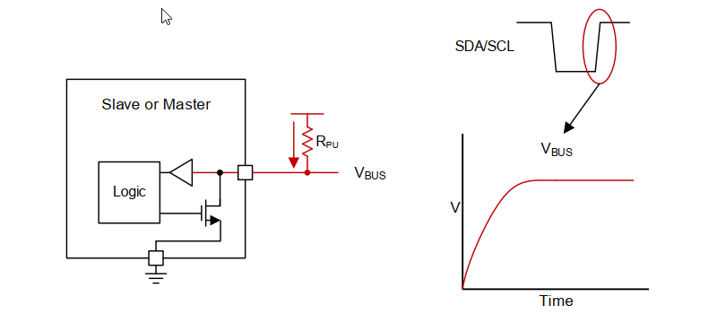
When logic HIGH needs to be transmitted the I2C hardware deactivates / tri-state the pull-down FET to disconnect the bus line from GND. This leaves the bus floating, and the pull-up resistor will pull the voltage up to the power rail, which will be interpreted as a HIGH.
I²C Bus Protocol
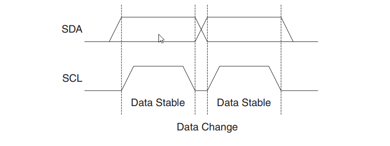
Each data bit transferred on the I2C bus is accompanied by a pulse on the clock line. The level of the data line must be stable when the clock line is HIGH. The only exception to this rule is for generating START and STOP conditions.
A HIGH-to-LOW transition on the SDA line, while the SCL is HIGH, defines a START condition.
A LOW-to-HIGH transition on the SDA line, while the SCL is HIGH, defines a STOP condition.
The Master initiates and terminates a data transmission. The transmission is initiated when the Master issues a START condition on the bus, and it is terminated when the Master issues a STOP condition. Between a START and a STOP condition, the bus is considered busy, and no other master should try to seize control of the bus. Data transfer may be initiated only when the bus is idle. A bus is considered idle if both SDA and SCL lines are HIGH after a STOP condition.
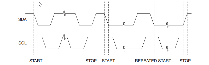
A special case occurs when a new START condition is issued between a START and STOP condition. This is referred to as a REPEATED START condition. After a REPEATED START, the bus is considered busy until the next STOP. This is identical to the START behavior, and therefore START is used to describe both START and REPEATED START. This is useful for when the master wishes to start a new communication but does not wish to let the bus go idle with the STOP condition, which has the chance of the master losing control of the bus to another master (in multi-master environments)
One data bit is transferred during each clock pulse of the SCL. Data is transferred byte by byte. Data is transferred Most Significant Bit (MSB) first. Any number of data bytes can be transferred from the master to slave between the START and STOP conditions. Usually, Data on the SDA line must remain stable during the HIGH phase of the clock period, as changes in the data line when the SCL is HIGH are interpreted as control commands (START or STOP).
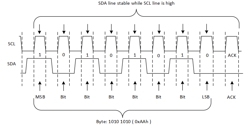
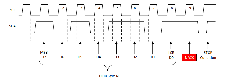
Each byte of data is followed by one ACK / NACK bit from the receiver. The ACK bit allows the receiver to communicate to the transmitter that the byte was successfully received and another byte may be sent. Before the receiver can send an ACK, the transmitter must release the SDA line. An acknowledge (ACK) is signaled by the Receiver pulling the SDA line LOW during the ninth SCL cycle. If the receiver leaves the SDA line HIGH, a not acknowledge (NACK) is signaled.
There are several conditions that lead to the generation of a NACK:
- The receiver is unable to receive or transmit because it is performing some real-time function and is not ready to start communication with the master
- During the transfer, the receiver gets data or commands that it does not understand
- During the transfer, the receiver cannot receive any more data bytes
- A master-receiver is done reading data and indicates this to the slave through a NACK
Clock Stretching by Slave Devices
When a slave device holds the clock line (SCL) LOW after receiving (or sending) a byte it is called clock stretching. This usually indicates that it is not yet ready to process more data. The master must wait until the clock line actually goes HIGH. Clock stretching is the only time in I2C where the slave drives SCL. This is possible due to open-drain / open-collector pins. Many slaves do not need to clock stretch and thus treat SCL as strictly an input with no circuitry to drive it. Some masters may not support clock stretching and are labeled as a “two-wire interface” and not I2C.
I²C Modes
- Standard Mode
Standard mode refers to the initial transfer speed mode of the I2C specification which allows up to 100 kbit/s. - Fast Mode
Fast mode tightens several of the timing parameters to achieve 400 kbit/s speed. Fast mode is widely supported by I2C slave devices, so a master may use it as long as it knows that the bus capacitance and pull-up strength allow it. - Fast Mode Plus (FM+)
Fast mode plus supports up to 1 Mbit/s using more powerful drivers and pull-ups to achieve faster rise and fall times. Fast mode plus devices are downward compatible with standard and fast mode devices. - High Speed Mode (HS)
High speed mode of the I2C bus allows communication up to 3.4 Mbit/s. In order to support high frequency HS mode master devices have a combination of an open-drain pull-down and current-source pull-up circuit on the SCL output. - Ultra Fast Mode
Ultra fast mode only supports one master, and it actively drives both clock and data lines at all times to achieve a 5 Mbit/s transfer rate. Clock stretching, arbitration, read transfers, and acknowledgements are all omitted. It is mainly intended for applications where a transmission error would not cause catastrophic failure. This is also incompatible with other modes.
I²C Read and Write
There are two types of data packets that are transferred on an I2C bus. They are :
- Address Packet (Transmitted by master)
- Data Packet (Transmitted by both master and slave)
Address Packet Format
All address packets transmitted on the I2C bus are 9 bits long, consisting of 7 bit slave addresses (SLA), one READ/WRITE control bit and an acknowledge bit (ACK / NACK). The First 8 bits (SLA+R / SLA+W) are transmitted from the master and the last bit is transmitted from the slave.
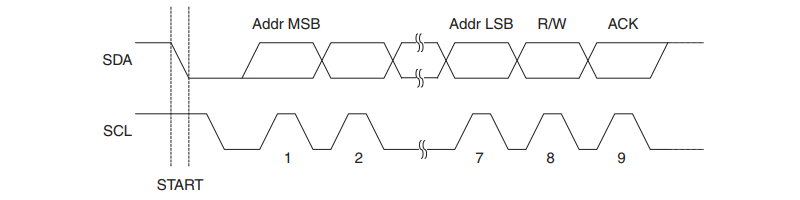
If the READ/WRITE bit is set, a read operation is to be performed on the slave, otherwise, a write operation should be performed on the slave. When a Slave recognizes that it is being addressed, it should reply by ACK, if it is busy it should reply by NACK. The master can then transmit a STOP condition, or a REPEATED START condition to initiate a new transmission.
The address 0b0000 000 is reserved for a general call. When a general call is issued, all slaves should respond by pulling the SDA line LOW in the ACK cycle. A general call is used when a Master wishes to transmit the same message to several slaves in the system. Note that transmitting the general call address followed by a read bit is meaningless, as this would cause a communication clash if several slaves started transmitting different data.
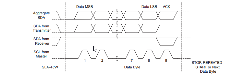
Data Packet Format
All data packets transmitted on the I2C bus are nine bits long, consisting of one data byte and an acknowledge bit (ACK / NACK). The first 8 bits are transmitted from the transmitter and the last bit is transmitted from the receiver. The receiver can reply with ACK or NACK based on the data or its state on the ninth clock cycle of SCK. When the receiver has received the last byte, or for some reason cannot receive any more bytes, it should inform the Transmitter by sending a NACK after the final byte.
Multi Master Bus Systems
I2C allows multiple masters to be present on the bus and can share the same slave device. But multiple masters sharing the same SDA and SCL bus lines can lead to communication clashes and data corruption. To solve such problems two algorithms are used :
- Synchronization [of SCL]
- Arbitration [of SDA]
Synchronization
Different masters may use different SCL frequencies and may differ in phase. A scheme must be devised to synchronize the serial clocks from all masters, in order to let the transmission proceed in a lockstep fashion.
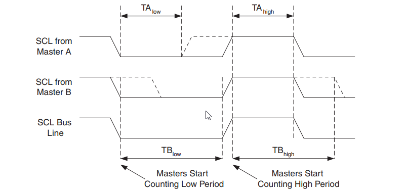
The wired-ANDing of the bus lines is used to solve this problem. The serial clocks from all masters will be wired-ANDed, yielding a combined clock with a HIGH period equal to the one from the Master with the shortest HIGH period. The LOW period of the combined clock is equal to the LOW period of the master with the longest LOW period. All masters listen to the SCL line, effectively starting to count their SCL HIGH and LOW time-out periods when the combined SCL line goes HIGH or LOW, respectively.
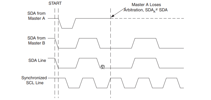
Arbitration
Two masters can try to start transmission at the same time. Only one of the masters is allowed to complete the transmission. All other masters should cease transmission when they discover that they have lost the selection process. This selection process is called arbitration. Arbitration is carried out by all masters continuously monitoring the SDA line after outputting data. If the value read from the SDA line does not match the value the master had output, it has lost the arbitration. Note that a master can only lose arbitration when it outputs a HIGH SDA value while another master outputs a LOW value. The losing Master should immediately switch to Slave mode to check whether it is being addressed by the winning master.
Note that arbitration is not allowed between:
- A REPEATED START condition and a data bit
- A STOP condition and a data bit
- A REPEATED START and a STOP condition
All transmissions must contain the same number of data packets, otherwise, the result of the arbitration is undefined.
Advantages
- Half duplex communication
- Open-drain or Open-collector drivers / pins
- Uses 2 wires
- Slave acknowledgement
- Multi master protocol
Disadvantages
- Slaves in the same bus may not support a common mode / transmission speed
- Low throughput
- Short distance communiaction
- Strict bus capacitance and length parameters
- Faulty slave can hold the bus LOW, which hangs the entire bus as the same bus lines are shared
- I2C bus segments are implemented when many slaves ae present in the bus system


1 Comment
Helmut Weingart · December 20, 2022 at 7:54 pm
Hallo, I started with low level programming. There have been to much to understand what is I2C. I looked at the arduino libs and read the code. But I did not completely know what is really happening.
Thank you very much for your instructions. It is very, very, really very good explained. Your tutorials should not be missed at any university !
I implement a library (WAM – SAM) Tool-Automat-Material Metapher – State-Automats-Materials for very high reuse in embedded development.
I try to prove that OO Concepts can even be used in embedded development.
Thank you.