Note
This article is a part of Arduino / ATmega328p Embedded C Firmware Programming Tutorial. Consider exploring the course home page for articles on similar topics.

Arduino Tutorial Embedded C Register Level Arduino Master Class
Also visit the Release Page for Register Level Embedded C Hardware Abstraction Library and Code for AVR.
Introduction
In this article, we are discussing the ATmega328P analog comparator hardware feature.
What You Will Learn
- How the internal Analog Comparator works in Arduino?
- Which Registers control the Analog Comparator of AVR ATmega328p?
- How Analog Comparator is enabled in ATmega328p?
Analog Comparator
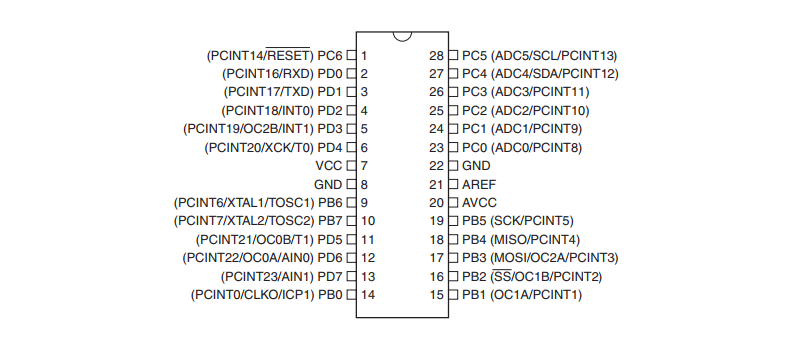
The Analog Comparator compares the input values on the positive pin AIN0 and negative pin AIN1. When the voltage on the positive pin AIN0 is higher than the voltage on the negative pin AIN1, the Analog Comparator output, ACO, is set. The comparator’s output can be set to trigger the Timer/Counter1 Input Capture function. In addition, the comparator can trigger a separate interrupt, exclusive to the Analog Comparator. The user can select Interrupt triggering on comparator output rise, fall, or toggle.

The Power Reduction ADC bit, PRADC must be disabled by writing a logical zero to be able to use the ADC input MUX.
Analog Comparator Multiplexed Input
It is possible to select any of the ADC7…0 pins to replace the negative input to the Analog Comparator. The ADC multiplexer is used to select this input, and consequently, the ADC must be switched off to utilize this feature. If the Analog Comparator Multiplexer Enable bit (ACME in ADCSRB) is set and the ADC is switched off (ADEN in ADCSRA is zero), MUX2…0 in ADMUX select the input pin to replace the negative input to the Analog Comparator. If ACME is cleared or ADEN is set, AIN1 is applied to the negative input to the Analog Comparator.
| ACME | ADEN | MUX2…0 | Analog Comparator Negative Input |
|---|---|---|---|
| 0 | x | xxx | AIN1 |
| 1 | 1 | xxx | AIN1 |
| 1 | 0 | 000 | ADC0 |
| 1 | 0 | 001 | ADC1 |
| 1 | 0 | 010 | ADC2 |
| 1 | 0 | 011 | ADC3 |
| 1 | 0 | 100 | ADC4 |
| 1 | 0 | 101 | ADC5 |
| 1 | 0 | 110 | ADC6 |
| 1 | 0 | 111 | ADC7 |
Register Description
ADCSRB – ADC Control and Status Register B
| Bit | 7 | 6 | 5 | 4 | 3 | 2 | 1 | 0 |
| Read/Write | R | R/W | R | R | R | R/W | R/W | R/W |
| Initial Value | 0 | 0 | 0 | 0 | 0 | 0 | 0 | 0 |
| (0x7B) | – | ACME | – | – | – | ADTS2 | ADTS1 | ADTS0 |
- Bit 6 – ACME: Analog Comparator Multiplexer Enable
When this bit is written logic one and the ADC is switched off (ADEN in ADCSRA is zero), the ADC multiplexer selects the negative input to the Analog Comparator. When this bit is written logic zero, AIN1 is applied to the negative input of the Analog Comparator.
ACSR – Analog Comparator Control and Status Register
| Bit | 7 | 6 | 5 | 4 | 3 | 2 | 1 | 0 |
| Read/Write | R/W | R/W | R | R/W | R/W | R/W | R/W | R/W |
| Initial Value | 0 | 0 | N/A | 0 | 0 | 0 | 0 | 0 |
| 0x30 (0x50) | ACD | ACBG | ACO | ACI | ACIE | ACIC | ACIS1 | ACIS0 |
- Bit 7 – ACD: Analog Comparator Disable
When this bit is written logic one, the power to the Analog Comparator is switched off. - Bit 6 – ACBG: Analog Comparator Bandgap Select
When this bit is set, a fixed bandgap reference voltage replaces the positive input to the Analog Comparator. When this bit is cleared, AIN0 is applied to the positive input of the Analog Comparator. - Bit 5 – ACO: Analog Comparator Output
The output of the Analog Comparator is synchronized and then directly connected to ACO. - Bit 4 – ACI: Analog Comparator Interrupt Flag
This bit is set by hardware when a comparator output event triggers the interrupt mode defined by ACIS1 and ACIS0. - Bit 3 – ACIE: Analog Comparator Interrupt Enable
When the ACIE bit is written logic one and the I-bit in the Status Register is set, the Analog Comparator interrupt is activated. When written logic zero, the interrupt is disabled. - Bit 2 – ACIC: Analog Comparator Input Capture Enable
When written logic one, this bit enables the input capture function in Timer/Counter1 to be triggered by the Analog Comparator. When written logic zero, no connection between the Analog Comparator and the input capture function exists. - Bits 1, 0 – ACIS1, ACIS0: Analog Comparator Interrupt Mode Select
These bits determine which comparator events that trigger the Analog Comparator interrupt.
| ACIS1 | ACIS0 | Interrupt Mode |
|---|---|---|
| 0 | 0 | Comparator Interrupt on Output Toggle. |
| 0 | 1 | Reserved |
| 1 | 0 | Comparator Interrupt on Falling Output Edge. |
| 1 | 1 | Comparator Interrupt on Rising Output Edge. |
DIDR1 – Digital Input Disable Register 1
| Bit | 7 | 6 | 5 | 4 | 3 | 2 | 1 | 0 |
| Read/Write | R | R | R | R | R | R | R/W | R/W |
| Initial Value | 0 | 0 | 0 | 0 | 0 | 0 | 0 | 0 |
| (0x7F) | – | – | – | – | – | – | AIN1D | AIN0D |
- Bit 7:2 – Reserved
These bits are unused bits and will always read as zero. - Bit 1, 0 – AIN1D, AIN0D: AIN1, AIN0 Digital Input Disable
When this bit is written logic one, the digital input buffer on the AIN1/0 pin is disabled.


0 Comments