Note
This article is a part of Arduino / ATmega328p Embedded C Firmware Programming Tutorial. Consider exploring the course home page for articles on similar topics.

Arduino Tutorial Embedded C Register Level Arduino Master Class
Also visit the Release Page for Register Level Embedded C Hardware Abstraction Library and Code for AVR.
Introduction
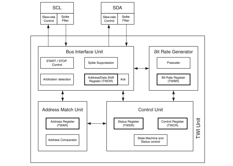
The I2C / 2-wire Serial Interface (TWI) hardware in the ATmega48A/PA/88A/PA/168A/PA/328/P microcontroller uses registers TWBR, TWCR, TWSR, TWDR, TWAR, and TWAMR to configure the hardware and to transmit and receive data. Below are the register descriptions. Atmel uses the term TWI / Two Wire Interface for avoiding licensing conflicts. TWI is compatible with the I2C protocol.
What You Will Learn
- What are the I2C Registers in Arduino?
- What are the I2C Registers in AVR ATmega328p?
- Which AVR Registers control and configures I2C / TWI / Two Wire Interface?
- What is the function of the AVR I2C Registers?
TWBR – TWI Bit Rate Register
| Bit | 7 | 6 | 5 | 4 | 3 | 2 | 1 | 0 |
| 0xB8 | TWBR7 | TWBR6 | TWBR5 | TWBR4 | TWBR3 | TWBR2 | TWBR1 | SPR0 |
| Read/Write | R/W | R/W | R/W | R/W | R/W | R/W | R/W | R/W |
| Initial Value | 0 | 0 | 0 | 0 | 0 | 0 | 0 | 0 |
• Bits 7…0 – TWI Bit Rate Register
TWBR selects the division factor for the bit rate generator. The bit rate generator is a frequency divider that generates the SCL clock frequency in the Master modes.
SCL frequency = CPU clock frequency / (16 + 2 * TWBR * PrescalerValue)
TWCR – TWI Control Register
| Bit | 7 | 6 | 5 | 4 | 3 | 2 | 1 | 0 |
| 0xBC | TWINT | TWEA | TWSTA | TWSTO | TWWC | TWEN | – | TWIE |
| Read/Write | R/W | R/W | R/W | R/W | R/W | R/W | R/W | R/W |
| Initial Value | 0 | 0 | 0 | 0 | 0 | 0 | 0 | 0 |
The TWCR is used to control the operation of the I2C / TWI. It is used to enable the I2C / TWI, to initiate a Master access by applying a START condition to the bus, to generate a Receiver acknowledge, to generate a STOP condition, and to control bus collisions.
• Bit 7 – TWINT: TWI Interrupt Flag
This bit is set by hardware when the TWI has finished its current job and expects an application software response. When the TWINT Flag is set, the SCL LOW period is stretched. The TWINT Flag must be cleared by software by writing a logical one to it. This flag is not automatically cleared by hardware when executing the interrupt routine. Clearing this flag resumes the operation of the TWI.
• Bit 6 – TWEA: TWI Enable Acknowledge Bit
The TWEA bit controls the generation of the acknowledged pulse. If the TWEA bit is written to one, the ACK pulse is generated on the TWI bus if the following conditions are met:
1. The device’s own slave address has been received
2. A general call has been received, while the TWGCE bit in the TWAR is set
3. A data byte has been received in master receiver or slave receiver mode
By writing the TWEA bit to zero, the device can be disconnected from the 2-wire serial bus temporarily.
• Bit 5 – TWSTA: TWI START Condition Bit
The application software needs to write the TWSTA bit to one when it desires to become a master on the 2-wire Serial Bus. The TWI hardware generates a START condition on the bus if it is free. If the bus is not free, the TWI waits until a STOP condition is detected, and then generates a new START condition to claim the bus master status. TWSTA must be cleared by software when the START condition has been transmitted.
• Bit 4 – TWSTO: TWI STOP Condition Bit
When the TWSTO bit is set the TWi hardware will generate a STOP condition on the 2-wire bus. When the STOP condition is executed on the bus, the TWSTO bit is cleared automatically. In slave mode, setting the TWSTO bit is used to recover from an error condition. This releases the SCL and SDA lines to a high impedance state.
• Bit 3 – TWWC: TWI Write Collision Flag
The TWWC bit is set when attempting to write to the TWI Data Register – TWDR when TWINT is low. This flag is cleared by writing the TWDR Register when TWINT is high.
• Bit 2 – TWEN: TWI Enable Bit
The TWEN bit enables I2C / TWI operation and activates the TWI interface. If this bit is written to zero, the TWI is switched off and all TWI transmissions are terminated, regardless of any ongoing operation.
• Bit 1 – Reserved
This bit is a reserved bit and will always read as zero.
• Bit 0 – TWIE: TWI Interrupt Enable
When this bit is written to one, and the I-bit in SREG is set, the TWI interrupt is enabled.
TWSR – TWI Status Register
| Bit | 7 | 6 | 5 | 4 | 3 | 2 | 1 | 0 |
| (0xB9) | TWS7 | TWS6 | TWS5 | TWS4 | TWS3 | – | TWPS1 | TWPS0 |
| Read/Write | R | R | R | R | R | R | R/W | R/W |
| Initial Value | 1 | 1 | 1 | 1 | 1 | 1 | 1 | 1 |
• Bits 7:3 – TWS: TWI Status
These 5 bits reflect the status of the TWI logic and the 2-wire serial bus.
• Bit 2 – Reserved
This bit is reserved and will always read as zero.
• Bits 1:0 – TWPS: TWI Prescaler Bits
These bits can be read and written, and control the bit rate Prescaler
| TWPS1 | TWPS0 | Prescaler Value |
| 0 | 0 | 1 |
| 0 | 1 | 4 |
| 1 | 0 | 16 |
| 1 | 1 | 64 |
TWDR – TWI Data Register
| Bit | 7 | 6 | 5 | 4 | 3 | 2 | 1 | 0 |
| (0xBB) | TWD7 | TWD6 | TWD5 | TWD4 | TWD3 | TWD2 | TWD1 | TWD0 |
| Read/Write | R/W | R/W | R/W | R/W | R/W | R/W | R/W | R/W |
| Initial Value | 1 | 1 | 1 | 1 | 1 | 1 | 1 | 1 |
In Transmit mode, TWDR contains the next byte to be transmitted. In Receive mode, the TWDR contains the last byte received. Data can be written when the TWI Interrupt Flag (TWINT) is set by hardware. The data in TWDR remains stable as long as TWINT is set. While data is shifted out on the bus. In the case of lost bus arbitration, no data is lost in the transition from master to slave. Handling of the ACK bit is controlled automatically by the TWI logic, the CPU cannot access the ACK bit directly.
• Bits 7:0 – TWD: TWI Data Register
These eight bits constitute the next data byte to be transmitted or the latest data byte received on the 2-wire Serial Bus.
TWAR – TWI (Slave) Address Register
| Bit | 7 | 6 | 5 | 4 | 3 | 2 | 1 | 0 |
| (0xBA) | TWA6 | TWA5 | TWA4 | TWA3 | TWA2 | TWA1 | TWA0 | TWGCE |
| Read/Write | R/W | R/W | R/W | R/W | R/W | R/W | R/W | R/W |
| Initial Value | 1 | 1 | 1 | 1 | 1 | 1 | 1 | 0 |
The TWAR should be loaded with the 7-bit slave address (in the seven most significant bits of TWAR) to which the TWI will respond when programmed as a slave transmitter or receiver, and not needed in the master modes. In
multi master systems, TWAR must be set.
• Bits 7:1 – TWA: TWI (Slave) Address Register
These seven bits constitute the slave address of the TWI unit.
• Bit 0 – TWGCE: TWI General Call Recognition Enable Bit
If set, this bit enables the recognition of a General Call given over the 2-wire Serial Bus.
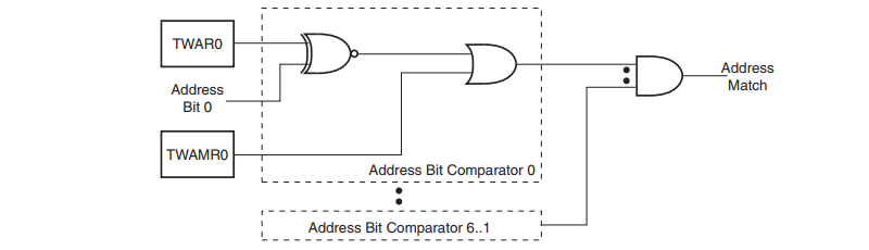
TWAMR – TWI (Slave) Address Mask Register
| Bit | 7 | 6 | 5 | 4 | 3 | 2 | 1 | 0 |
| (0xBA) | TWAM6 | TWAM5 | TWAM4 | TWAM3 | TWAM2 | TWAM1 | TWAM0 | – |
| Read/Write | R/W | R/W | R/W | R/W | R/W | R/W | R/W | R/W |
| Initial Value | 0 | 0 | 0 | 0 | 0 | 0 | 0 | 0 |
• Bits 7:1 – TWAM: TWI Address Mask
The TWAMR can be loaded with a 7-bit Salve Address mask. Each of the bits in TWAMR can mask (disable) the corresponding address bits in the TWI Address Register (TWAR). If the mask bit is set to one then the address
match logic ignores the comparison between the incoming address bit and the corresponding bit in TWAR.
• Bit 0 – Reserved
This bit is an unused bit in the ATmega48A/PA/88A/PA/168A/PA/328/P, and will always read as zero.


0 Comments