Note
This article is a part of Arduino / ATmega328p Embedded C Firmware Programming Tutorial. Consider exploring the course home page for articles on similar topics.

Arduino Tutorial Embedded C Register Level Arduino Master Class
Also visit the Release Page for Register Level Embedded C Hardware Abstraction Library and Code for AVR.
Introduction
The Universal Synchronous and Asynchronous Receiver and Transmitter (USART) is a full duplex or half duplex or simplex transmitter or simplex receiver which can be used in synchronous or asynchronous serial communication mode and is used for short-distance communication, primarily in embedded systems. The interface was developed by Gordon Bell at Digital Equipment Corporation in the 1960s. The USART communication is a master-slave protocol with a single master device and single slave devices. USART is used for communicating with microcontrollers, microprocessors, GPS modules, GSM modules, keyboard, sensors (Gyroscope, etc.) and is widely used in modern day embedded systems.
When USART (Universal Synchronous and Asynchronous Receiver and Transmitter) is used in the asynchronous mode it is called UART (Universal Asynchronous Receiver and Transmitter).
What You Will Learn
- How does USART/UART communication work in Arduino?
- How does USART/UART communication work in AVR ATmega328p?
- What are the Pros and Cons of USART/UART communication?
- What is the USART/UART Data Frame format?
USART Features
- Full duplex or half duplex or simplex reception or simplex transmission communication
- Single master – single slave architecture
- Asynchronous or synchronous operation
- Master or slave clocked synchronous operation
- High speed communication [usually kHz, rarely MHz]
- Push-pull hardware pin drivers
- Two or three wire / pin serial bus
- TxD/ Transmit Data – Output data from the master or slave device to the RxD pin of the slave or master device
- RxD/ Receive Data – Input data from a TxD pin of master or slave device to the slave or master device
- XCK/ Transfer Clock – Clock driven by the master device, used to synchronize the data bits and used only in synchronous mode
- Parity generator, parity checker and framing error handeling in hardware
- Flexible data length, framing and error handeling
- Short to mid distance communication, usually on the same PCB / system / peripherals
| Term | Description |
|---|---|
| Master | The device that initiates and terminates a transmission |
| Slave | The device connected to a master |
| Transmitter | The device placing data on the bus |
| Receiver | The device reading data from the bus |
USART Bus Hardware
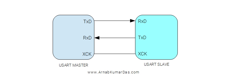
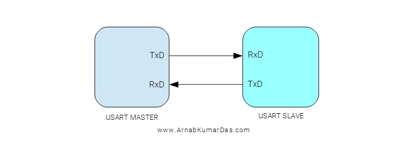
USART bus uses two wires/pins when used in asynchronous mode and uses three wires/pins in synchronous mode to communicate between two devices. The three wires/pins are TxD, RxD, and XCK. Data flows out through the TxD and flows in through the RxD pin. The XCX pin is used to synchronize the data transfer by supplying a clock signal only in synchronous communication mode. TxD pin in the master is connected to RxD pin in slave and vice versa. Simplex transmission or reception mode uses a single wire/pin in asynchronous mode.
The transmitter consists of a single write buffer, a serial shift register, a parity generator, and control logic for handling different serial frame formats. The write buffer allows a continuous transfer of data without any delay between frames. The receiver is the most complex part of the USART module due to its clock and data recovery units. The recovery units are used for asynchronous data reception. In addition to the recovery units, the receiver includes a parity checker, control logic, a shift register, and a receive buffer. The Receiver supports the same frame formats as the transmitter and can detect frame error, data overrun, and parity errors.
USART Bus Clock and Baud
To begin any USART communication the first step is to configure the baud rate generator of the device. The baud rate of master and slave devices should be the same for error-free communication. Baud rate defines the transmission speed or data rate. Some valid baud rates (bps) are 2400, 4800, 9600, 14.4k, 19.2k, 28.8k, 38.4k, 57.6k, 76.8k, 115.2k, 230.4k, 250k, 0.5M, 1M. Out of these 9600bps, 115200bps are very popular in embedded systems.
In synchronous master mode, the device uses XCK pin to output the generated clock using the baud rate generator. In synchronous slave mode, the XCK pin is used to receive the external clock. External clock input from the XCK pin is sampled by a synchronization register to minimize the chance of metastability. The output from the synchronization register must then pass through an edge detector before it can be used by the transmitter and receiver. This sometimes leads to CPU clock period delay which reduces the bandwidth of the communication channel. The set baud rate depends on the hardware capability of both master and slave devices.
When the synchronous mode is used, the XCK pin will be used as either clock input (Slave) or clock output (Master). The dependency between the clock edges and data sampling or data change is the same. The basic principle is that data input (on RxD) is sampled at the opposite XCK clock edge of the edge the data output (TxD) is changed.
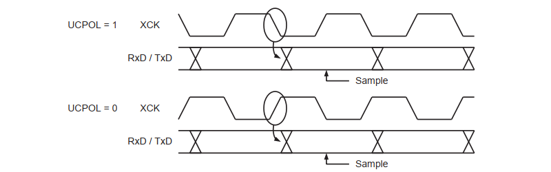
The UCPOL bit selects which XCK clock edge is used for data sampling and which is used for data change. When UCPOLn is zero the data will be changed at rising XCK edge and sampled at falling XCK edge. If UCPOL is set, the data will be changed at the falling XCK edge and sampled at the rising XCK edge.
USART Frame Format
A USART serial frame is defined to be one character of data bits with synchronization bits (start and stop bits), and optionally a parity bit for error checking. The USART has 30 combinations of valid frame formats:
- 1 start bit
- 5, 6, 7, 8, or 9 data bits
- no, even or odd parity bit
- 1 or 2 stop bits
A USART frame starts with the start bit followed by the (LSB) least significant data bit. Then the next data bits, up to a maximum of nine, ending with the (MSB) most significant bit. If enabled, the parity bit is inserted after the data bits, before the stop bits. When a complete frame is transmitted, it can be directly followed by a new frame, or the communication line can be set to an idle (high) state.
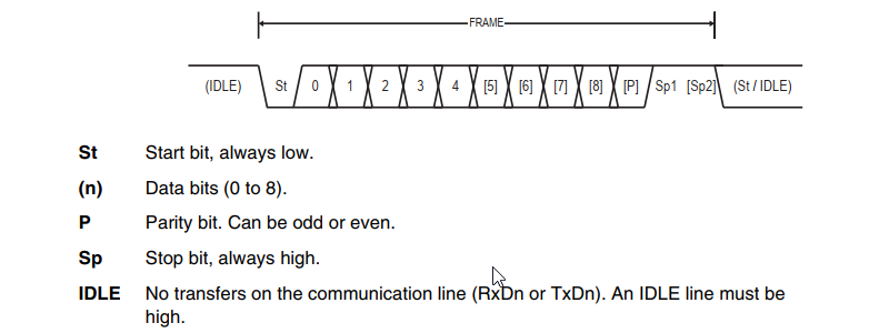
Bits inside brackets are optional. The receiver and transmitter use the same setting. The receiver ignores the second stop bit. An FE (Frame Error) will therefore only be detected in the cases where the first stop bit is zero.
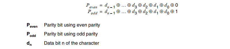
The parity bit is calculated by doing an exclusive-or of all the data bits. If odd parity is used, the result of the exclusive or is inverted. The relation between the parity bit and data bits is as follows:
USART Transmitter
The USART transmitter is enabled and configured by setting registers in the microcontroller. The baud rate, mode of operation, and frame format must be set up once before doing any transmissions. If synchronous operation is used, the XCK pin will be overridden and used as a transmission clock.
The application software loads the transmit buffer with valid data. The buffered data in the transmit buffer will be moved to the shift register when the shift register is ready to send a new frame. The shift register is loaded with new data if it is in an idle state (no ongoing transmission) or immediately after the last stop bit of the previous frame is transmitted.
When the shift register is loaded with new data, it will transfer one complete frame at the rate given by the baud rate generator.
The parity generator calculates the parity bit for the serial frame data. When the parity bit is enabled, the transmitter control logic inserts the parity bit between the last data bit and the first stop bit of the frame that is sent.
USART Receiver
The USART receiver is enabled and configured by setting registers in the microcontroller. The baud rate, mode of operation, and frame format must be set up once before any serial reception can be done. If synchronous operation is used, the clock on the XCK pin will be used as a transfer clock.
The Receiver starts data reception when it detects a valid start bit. Each bit that follows the start bit will be sampled at the baud rate or XCK clock, and shifted into the receive shift register until the first stop bit of a frame is
received. A second stop bit will be ignored by the receiver. When the first stop bit is received, i.e., a complete serial frame is present in the receive shift register, the contents of the shift register will be moved into the
receive buffer. The receive buffer can then be read by application software.
Parity checker calculates the parity of the data bits in incoming frames and compares the result with the parity bit from the serial frame. The result of the check is stored in the receive buffer or special register. Parity checking can be disabled if not used.
The USART receiver has three major error flags: frame error, data overrun, and parity error. All can be accessed by reading a special register in USART hardware. Sometimes the flags are present in the receive buffer together with the frame for which they indicate the error status. Application software can make decisions based on the error.
Asynchronous Clock and Data Recovery
The USART includes a clock recovery and a data recovery unit for handling asynchronous data reception. The clock recovery logic is used for synchronizing the internally generated baud rate clock to the incoming asynchronous serial frames at the RxD pin. The data recovery logic samples and low pass filters each incoming bit, thereby improving the noise immunity of the Receiver.
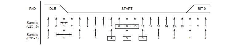
When the clock recovery logic detects a HIGH (idle) to LOW (start) transition on the RxD line, the start bit detection sequence is initiated. The clock recovery logic then samples the RxD line multiple times to decide if a valid start bit is received. If majority samples have logical high levels, the start bit is rejected as a noise spike and the receiver starts looking for the next high to low-transition. If however, a valid start bit is detected, the clock recovery logic is synchronized and the data recovery can begin. The synchronization process is repeated for each start bit.
When the receiver clock is synchronized to the start bit, the data recovery can begin. The data recovery unit uses a state machine to sample each bit.
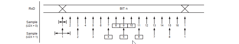
The decision of the logic level of the received bit is taken by doing a majority voting of the logic value if multiple samples in the center of the received bit. The majority voting process acts as a low pass filter for the incoming signal on the RxD pin. The recovery process is then repeated until a complete frame is received. Including the first stop bit. Note that the receiver only uses the first stop bit of a frame.
Transceiver Error Conditions
- Data Overrun Error
The data overrun indicates data loss due to a receiver buffer full condition. A data overrun occurs when the receive buffer is full, and a new byte is waiting in the receive shift register, and a new start bit is detected. - Underrun Error
An underrun error occurs when the UART transmitter has completed sending a byte and the transmit buffer is empty. In asynchronous modes this is treated as an indication that no data remains to be transmitted and is not an error. This error indication is commonly found in USARTs, since an underrun is more serious in synchronous systems. - Frame Error
The frame error indicates that STOP bit is not received when it is supposed to based on the timing of START bit. This flag can be used for detecting out-of-sync conditions, detecting break conditions and protocol handling. - Parity Error
The parity error indicates that the next frame in the receive buffer had a parity error when received.
Advantages
- Full duplex communication
- Can be configured in simplex and half duplex mode
- Push pull driver provides better signal integrity
- Variable data frame length
- Flexible wiring based on communication mode
- Simple software implementation
Disadvantages
- Short distance communiaction
- Single master protocol
- Single slave protocol


0 Comments