Introduction
This project is focused on designing our own Atmel AT89C51 Development Board that can be used for our learning and other projects. This project / Dev Board is compatible with Keil Professional PK51 DevKit. The focus of the project is to use cheap and readily available components to make a Development Board with a 8051 Microcontroller up and running.

Prerequisite
For this project, it is good to have basic knowledge of PCB designing and soldering components. This is not a very difficult project to do. A basic understanding of electronics is also benefitial to identify components and correctly assemble them.
Hardware bill of materials
Below is the list of materials that I have used for the project. It is highly encouraged to buy them directly from the link below or add them to cart.
- Soldering Station / Soldering Iron
- Soldering Flux
- Soldering Wire
- PCB Helping Hands
- Multimeter
- 8051 Programmer
- DC Jack x 1
- 7805 x 1
- 47uf Capacitor x 2
- 30pf Capacitor x 2
- 3mm LED x 1
- 330Ω Resistor x 1
- 10k Resistor x 1
- AT89C51 IC x 1
- Crystal Oscillator 12Mhz x 1
- 6mm Push Button x 1
- Male 2.54mm Header Connector x 1
- Female 2.54mm Header Connector x 2
Software bill of materials
Hardware description
8051 / AT89C51
The AT89C51 is a low-power, high-performance CMOS 8-bit microcomputer with 4Kbytes of Flash programmable and erasable read only memory (PEROM). The device is manufactured using Atmel’s high-density nonvolatile memory technology and is compatible with the industry-standard MCS-51 instruction set and pinout. The on-chip Flash allows the program memory to be reprogrammed in-system or by a conventional nonvolatile memory programmer. By combining a versatile 8-bit CPU with Flash on a monolithic chip, the Atmel AT89C51 is a powerful microcomputer which provides a highly-flexible and cost-effective solution to many embedded control applications.

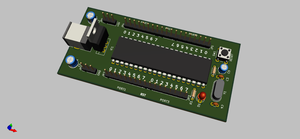
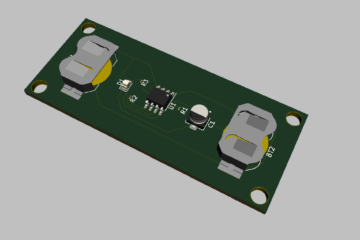
3D Render of 8051 / AT89C51 Development Board 3D Render of 8051 / AT89C51 Development Board

Software description
Eagle CAD
EAGLE is an electronic design automation (EDA) application with schematic capture, printed circuit board (PCB) layout, auto-router and computer-aided manufacturing (CAM) features. EAGLE and is developed by CadSoft Computer GmbH later in 2016 it was acquired by Autodesk Inc.
KiCad
KiCad (pronounced “Key-CAD”) is a free software suite for electronic design automation (EDA). It facilitates the design of schematics for electronic circuits and their conversion to PCB designs. It features an integrated environment for schematic capture and PCB layout design and also has tools within the package to create a bill of materials, artwork, Gerber files, and 3D views of the PCB and its components.
Keil PK51 Professional Developer Kit
The PK51 Professional Developer’s Kit for the 8051 microcontroller family supports all 8051 derivatives including new devices with extended memory and instruction sets (like the Dallas 390/5240/400, Philips 51MX, and Analog Devices MicroConverters) and classic devices and IP cores from companies like Analog Devices, Atmel, Cypress Semiconductor, Dallas Semiconductor, Goal, Hynix, Infineon, Intel, NXP (founded by Philips), OKI, Silicon Labs, SMSC, STMicroelectronics, Synopsis, TDK, Temic, Texas Instruments, and Winbond.
Schematic Design
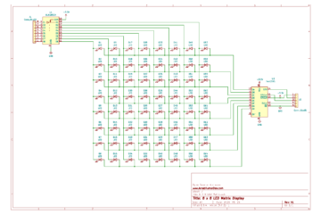
The below schematic is simple and doesn’t involve any complex circuitry. First the schematic is designed in Eagle CAD and later was imported into KiCad. Both the files are available for download at the end of the page. The schematic is divided in two major section one with the power and the other with the microcontroller.
The power section involves a LDO Voltage Regulator 7805. This provides stable 5V for the microcontroller. Recommended Input is from 7V – 9V.
The microcontroller section has the AT89C51 or AT89C52 or AT89S51 with all the port connections and other necessary passsive electronics.

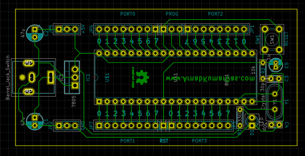
PCB Layout
The PCB Layout is completely designed in KiCad. A 3D view / render of the PCB is also available in KiCad.
All of the board is designed on bottom layer so it is easy to manufacture. It is so simple that it can be made with toner transfer method in home. It is also recommened to add ground plain on both the sides for better noise rejection.

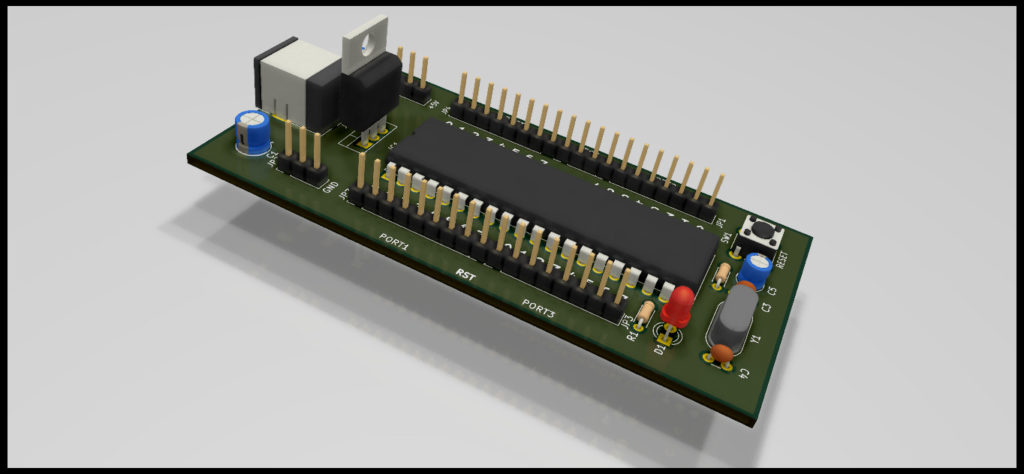
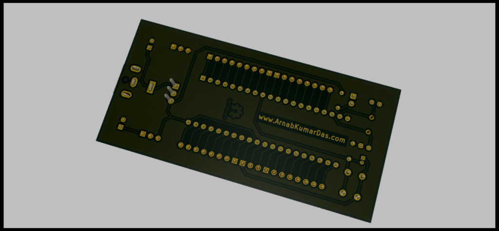
PCB layout of 8051 / AT89C51 Development Board 3D Raytrace Render of 8051 / AT89C51 Development Board 3D Raytrace Render of 8051 / AT89C51 Development Board 3D Raytrace Render of 8051 / AT89C51 Development Board

Conclusion
This particular project brings out learning about PCB design, component choices, cost of product planning and many more. Best thing about this project is it encourages DIY and Maker culture which is an amazing thing by itself. I encourage everyone to do this project and make your own Development Boards for their projects.
Scope of Improvement
I have mentioned this project as v1.0 as there are so many things to improve in this project. Things like improving the form factor to support Popular Modules, USB support, SMD design etc.
Download
Thanks for reading this project, I highly appreciate your time and effort.
1 Comment
Mehmed · July 12, 2022 at 10:41 pm
This is the project I was looking for. Thanks.