Introduction
This project is focused on designing and making our own L298 Motor Driver Module / Board that can be used for driving four / two DC Motor or one Stepper Motor or Solenoids. Motor Driver boards are widely used in Arduino, Raspberry Pi and other Mechatronics projects. This project / Driver Board is compatible with any microcontroller or microprocessor with 5V Logic. The focus of the project is to use cheap and readily available components to make a Motor Driver Module / Board with a L298 Driver IC. This IC supports 2A of continuous current for each channel. Even though it can take 3A peak current per channel it is not recommended to load the IC as it can overheat. Proper heatsink need to be installed to prevent damage to the IC.
Prerequisite
For this project, it is good to have basic knowledge of PCB designing and soldering components. This is not a very difficult project to do. A basic understanding of electronics is also benefitial to identify components and correctly assemble them.
Hardware bill of materials
Below is the list of materials that I have used for the project. It is highly encouraged to buy them directly from the link below or add them to cart.
- Soldering Station / Soldering Iron
- Soldering Flux
- Soldering Wire
- PCB Helping Hands
- Multimeter
- 7805 x 1
- 47uf Capacitor x 2
- 100nf Capacitor x 2
- 3mm LED x 1
- 330Ω Resistor x 1
- Male 2.54mm Header Connector x 1
- 01×03 Screw Terminal Connector x 3
- L298 IC
- 1N4007 Diode x 8
Software bill of materials
Hardware description
L298
The L298 is a high voltage, high current dual full-bridge driver. The L298 is designed to provide bidirectional drive currents of up to 4A at voltages from 2.5 V to 46 V. L298 IC is designed to drive inductive loads such as relays, solenoids, dc and bipolar stepping motors, as well as other high-current/high-voltage loads in positive-supply applications. When an enable input is high, the associated drivers are enabled, and their outputs are active and in phase with their inputs. When the enable input is low, those drivers are disabled, and their outputs are off and in the high-impedance state.
L298 is transistor based so it loses a lot of power as heat. It is typically 60-70% Efficient. If you are making a power critical project it is recommended to use CMOS Mosfet based Motor Driver they are much more efficient.
The motor speed in these below examples can be controlled by switching the drivers with pulse width modulated squarewaves. This approach is particularly suitable for microcontroller control. PWM generated from Arduino is one of the popular way to control the RPM of the motors.

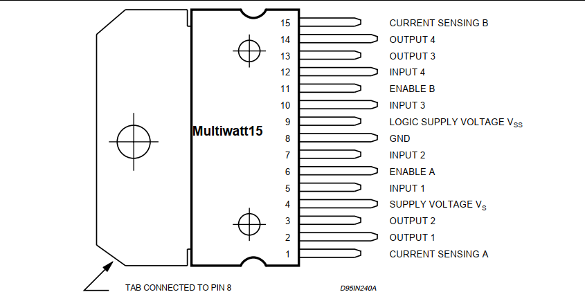
L298 IC Pin Diagram 
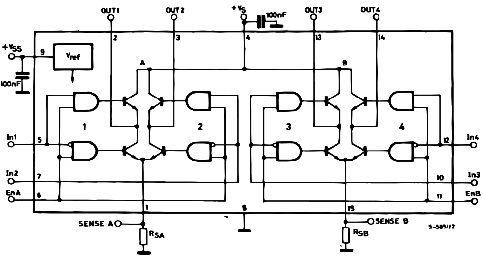
L298 IC Internal Block Diagram

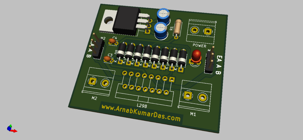
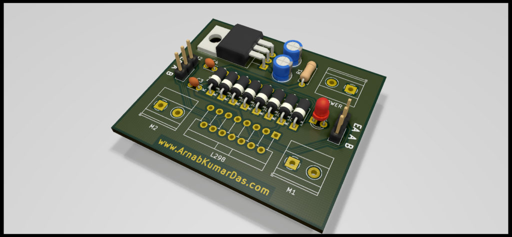
3D Render of L298 Motor Driver Module 3D Render of L298 Motor Driver Module
Software description
Eagle CAD
EAGLE is an electronic design automation (EDA) application with schematic capture, printed circuit board (PCB) layout, auto-router and computer-aided manufacturing (CAM) features. EAGLE and is developed by CadSoft Computer GmbH later in 2016 it was acquired by Autodesk Inc.
KiCad
KiCad (pronounced “Key-CAD”) is a free software suite for electronic design automation (EDA). It facilitates the design of schematics for electronic circuits and their conversion to PCB designs. It features an integrated environment for schematic capture and PCB layout design and also has tools within the package to create a bill of materials, artwork, Gerber files, and 3D views of the PCB and its components.
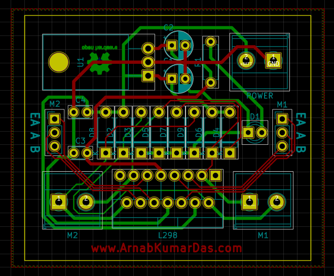
Schematic Design
The below schematic is simple and doesn’t involve any complex circuitry. First the schematic is designed in KiCad. The files are available for download at the end of the page. The schematic is divided in two major section one with the Power and the other with the Motor Driver IC.
The power section involves a LDO Voltage Regulator 7805. This provides stable 5V for the microcontroller. Recommended Input is 7V to 12V. Higher voltage is not recommeneded as 7805 will heat up much faster and can damage itself without a proper heatsink.
The Motor Driver section has the L298 IC with all the pin connections and other necessary passsive electronics. Four Supression Diodes are used for each motor to handel Back EMF. L298 has two power input one for driving the motors and one for logic operations. Filter Capacitors are added for both of the power input. A LED indicator is also added to glow when power is received at the board. This reduces debugging efforts when used in a project with multiple boards and hardware.
Sense pins are also present in L298. These pins are used for current sensing. Both the channel have their own sense pin.

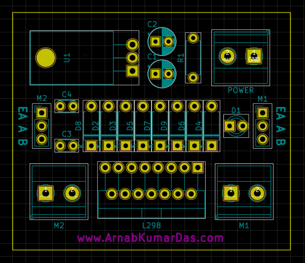
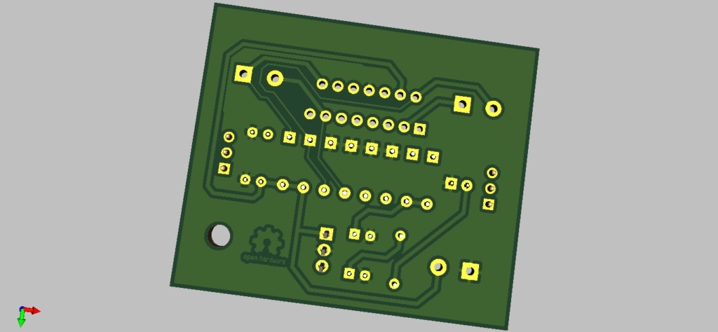
PCB Layout
The PCB Layout is completely designed in KiCad. A 3D view / render of the PCB is also available in KiCad. The L298 Motor Driver Module is designed to improve usability of the module itself.

PCB layout of L298 Motor Driver Module Ray Tracing Render of L298 Motor Driver Module Ray Tracing Render of L298 Motor Driver Module

Conclusion
This particular project brings out learning about PCB design, component choices, cost of product, planning and many more. Best thing about this project is it encourages DIY and Maker culture which is an amazing thing by itself. I encourage everyone to do this project and make your own Modules and Boards for their projects.
Scope of Improvement
I have mentioned this project as v1.0 as there are so many things to improve in this project. One of the main improvements that can be done is to use all SMD Components to reduce the formfactor, mounting holes, reverse polarity protection, etc.
Download
Thanks for reading this project, I highly appreciate your time and effort.
1 Comment
Salim · November 9, 2023 at 8:25 am
I tried this PCB circuit, but it doesn’t work, I’m using 6V battery. Please can you help me out?