Introduction
This project is focused on designing our own Atmega 16 / 32 Development Board that can be used for our learning and other projects. This project / Dev Board is compatible with Professional Atmel Studio. The focus of the project is to use cheap and readily available components to make a Development Board with a Microcontroller up and running.
Prerequisite
For this project, it is good to have basic knowledge of PCB designing and soldering components. This is not a very difficult project to do. A basic understanding of electronics is also benefitial to identify components and correctly assemble them.
Hardware bill of materials
Below is the list of materials that I have used for the project. It is highly encouraged to buy them directly from the link below or add them to cart.
- Soldering Station / Soldering Iron
- Soldering Flux
- Soldering Wire
- PCB Helping Hands
- Multimeter
- AVR USBasp – 6 Pin
- DC Jack x 1
- 7805 x 1
- 47uf Capacitor x 2
- 22pf Capacitor x 2
- 3mm LED x 1
- 330Ω Resistor x 1
- 10k Resistor x 1
- Atmega16 / 32 IC x 1
- Crystal Oscillator 16Mhz x 1
- 6mm Push Button x 1
- Male 2.54mm Header Connector x 1
- Female 2.54mm Header Connector x 2
Software bill of materials
Hardware description
AVR USBasp
USBasp is a USB in-circuit programmer for Atmel AVR controllers. It simply consists of an ATmega88 or an ATmega8 and a couple of passive components. The programmer uses a firmware-only USB driver, no special USB controller is used. USBasp is one of the cheapest and best programmer to use for programming 8-bit AVR devices. This will also save bytes of flash memory that Bootloader uses.
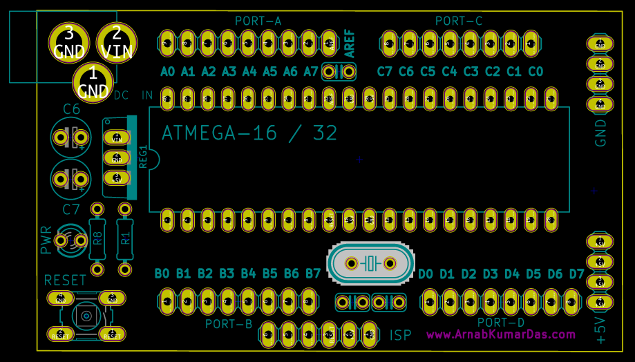
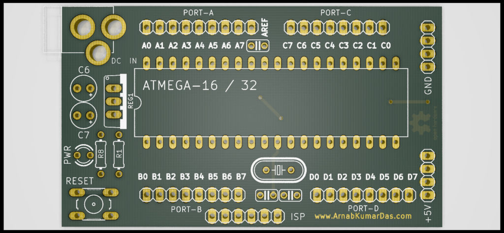
Atmega 16 / 32
Atmega 16 is a 40 Pin 16MIPS 8-Bit Microcontroller. It is originally designed and manufactured by Atmel but now it is manufactured by Microchip. Atmega 16 has 16KBytes of memory whereas Atmega 32 has 32KBytes of memory. It is very low cost and high performance, thus suits hobby as well as professional applications.
Software description
Eagle CAD
EAGLE is an electronic design automation (EDA) application with schematic capture, printed circuit board (PCB) layout, auto-router and computer-aided manufacturing (CAM) features. EAGLE and is developed by CadSoft Computer GmbH later in 2016 it was acquired by Autodesk Inc.
KiCad
KiCad (pronounced “Key-CAD”) is a free software suite for electronic design automation (EDA). It facilitates the design of schematics for electronic circuits and their conversion to PCB designs. It features an integrated environment for schematic capture and PCB layout design and also has tools within the package to create a bill of materials, artwork, Gerber files, and 3D views of the PCB and its components.
Atmel Studio
Atmel Studio 7 is the integrated development platform (IDP) for developing and debugging all AVR® microcontroller applications. The Atmel Studio 7 IDP easy-to-use environment to write, build and debug embedded applications written in C/C++ or assembly code. It also connects and support Arduino, USBasp and many other programmer and debugger. Moreover, this is the official development platform from Atmel / Microchip and is used by professionals, so we will be using this IDP.
Schematic Design
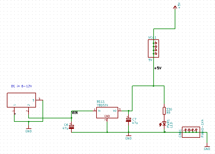
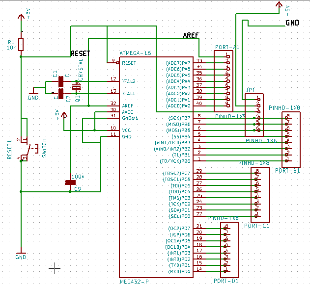
The below schematic is simple and doesn’t involve any complex circuitry. First the schematic is designed in Eagle CAD and later was imported into KiCad. Both the files are available for download at the end of the page. The schematic is divided in two major section one with the power and the other with the microcontroller.
The power section involves a LDO Voltage Regulator 7805. This provides stable 5V for the microcontroller. Recommended Input is from 7V – 9V.
The microcontroller section has the Atmega 16 or Atmega 32 with all the port connections and other necessary passsive electronics.

Power Section of Atmega 16-32 Development Board 
Microcontroller Section of Atmega 16-32 Development Board
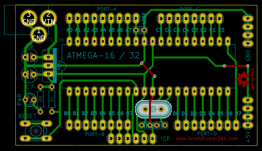
PCB Layout
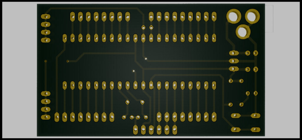
Similar steps are followed for the PCB layout as it is followed for schematic capture. Eagle CAD was used initially and later the file is imported into KiCad. A 3D view / render of the PCB is also available in KiCad.
Most of the board is designed on bottom layer so small jumpers can be used to replace the top layer tracks. It is also recommened to add ground plain on both the sides for better noise rejection.

PCB layout of Atmega 16-32 Development Board 
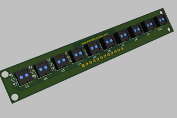
Ray Tracing Render of Atmega 16-32 Development Board Ray Tracing Render of Atmega 16-32 Development Board
Conclusion
This particular project brings out learning about PCB design, component choices, cost of product planning and many more. Best thing about this project is it encourages DIY and Maker culture which is an amazing thing by itself. I encourage everyone to do this project and make your own Development Boards for their projects.
Scope of Improvement
I have mentioned this project as v1.0 as there are so many things to improve in this project. Things like improving the form factor to support Popular Modules, USB support, SMD design etc.
Download
Thanks for reading this project, I highly appreciate your time and effort.
0 Comments