Note
This article is a part of Arduino / ATmega328p Embedded C Firmware Programming Tutorial. Consider exploring the course home page for articles on similar topics.

Arduino Tutorial Embedded C Register Level Arduino Master Class
Also visit the Release Page for Register Level Embedded C Hardware Abstraction Library and Code for AVR.
License
Copyright (c) 2014-2020 Arnab Kumar Das https://www.arnabkumardas.com/ You may freely modify and share this project and code, as long as you keep this notice intact (including the links). Licensed under the Creative Commons BY-SA 3.0 license:
http://creativecommons.org/licenses/by-sa/3.0/
Disclaimer: To the extent permitted by law, Arnab Kumar Das provides this work without any warranty. It might be defective, in which case you agree to be responsible for all resulting costs and damages.
Introduction
In this tutorial, we will learn how to interface a Zener based temperature sensor / LM335 / LMx35 with Arduino / Atmega328p. For this tutorial, we will be using the ADC and USART hardware peripheral of the Arduino / Atmega328p. The concepts learned in this tutorial can also be applied to other projects involving ADC and environmental sensing,
In this tutorial, we will first understand how the temperature sensor works, and later we will programming the Arduino / Atmeg328p and read the temperature on the serial terminal.
The programming and code in this tutorial can be done in both Atmel Studio and Arduino IDE.
What You Will Learn
- How to Program and Interface LM335 Temperature Sensor with Arduino?
- How to use Temperature Sensor with AVR ATmega328p?
- How to use ADC to read Teamperature in Arduino/ATmega328p?
- How to Program ADC and UART to interface Temperature Sensor in Arduino?
Prerequisite
Hardware Bill of Materials
- ATmega48A/PA/88A/PA/168A/PA/328/P or Arduino UNO/NANO/MINI
- USB ASP / Atmel ICE (if Arduino’s serial programming is not used)
- Dupont wire male to male
- Resistor 25K Ohms
- Breadboard
- LM335
Software Bill of Materials
- Atmel Studio / Arduino IDE
- Drivers
Hardware Description
LM335
The LMx35 series are precision integrated-circuit temperature sensors. Operating as a 2-terminal Zener, the LM335 has a breakdown voltage directly proportional to absolute temperature at 10 mV/°K. With less than 1-Ω dynamic impedance, the device operates over a current range of 400 µA to 5 mA with virtually no change in performance. The LM135 has a linear output. The LM335 operates from –40°C to 100°C. The LM135 has two functional modes calibrated and uncalibrated. In this tutorial, we will be running it in uncalibrated mode. For product design, the calibrated mode is recommended.
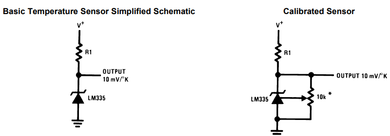
LM335 comes directly calibrated to the Kelvin temperature scale. At 25°C the accuracy is ±1°C but Accuracy from –55 °C to 150 °C is ±2.7°C.
Zener Diode
A Zener diode is a special type of diode designed to reliably allow current to flow “backward” through the p-n junction when a certain set reverse voltage, known as the Zener voltage, is reached.

Zener diodes are widely used as voltage references and as shunt regulators to regulate the voltage across small circuits. When connected in parallel with a variable voltage source so that it is reverse biased, a Zener diode conducts when the voltage reaches the diode’s reverse breakdown voltage. From that point on, the low impedance of the diode keeps the voltage across the diode at that value.
The voltage at which the Zener breakdown happens depends on the doping of the diode.
In the case of Zener based temperature sensor like LM335, the breakdown voltage varies with the temperature. The breakdown voltage of LM335 increases with an increase in temperature. At 0°C the breakdown voltage is around 2731mV and at 100°C it is around 3731mV.
Schematic Design
In this tutorial or experiment, we will be using the LM335 in a Zener voltage regulator configuration where the variable breakdown voltage of the LM335 will change the voltage drop and that can be further captured by the ADC. This configuration can be compared with a voltage divider but in this case, the voltage at VO is because of Zener breakdown.
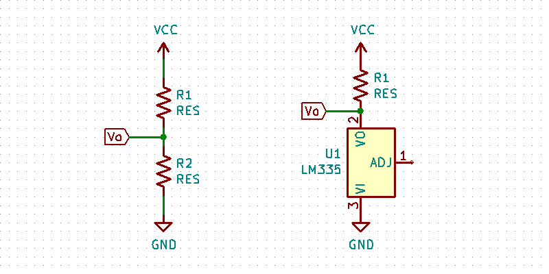

For optimum accuracy, R1 is picked such that 1mA flows through the sensor. An additional error can be introduced by varying load currents or varying supply voltage. The influence of these currents on the minimum and maximum reverse current flowing through the LM335 should be calculated and be maintained in the range of 0.4 mA to 5 mA. I have used 2K resistor for R1. It is recommended to measure the current and keep it under the limit of 1mA for optimum accuracy.
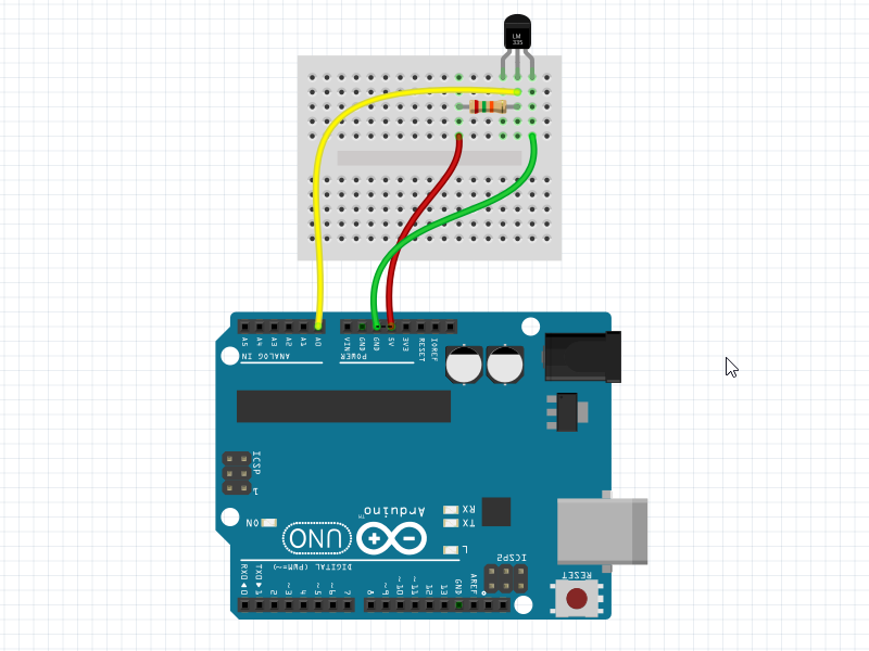
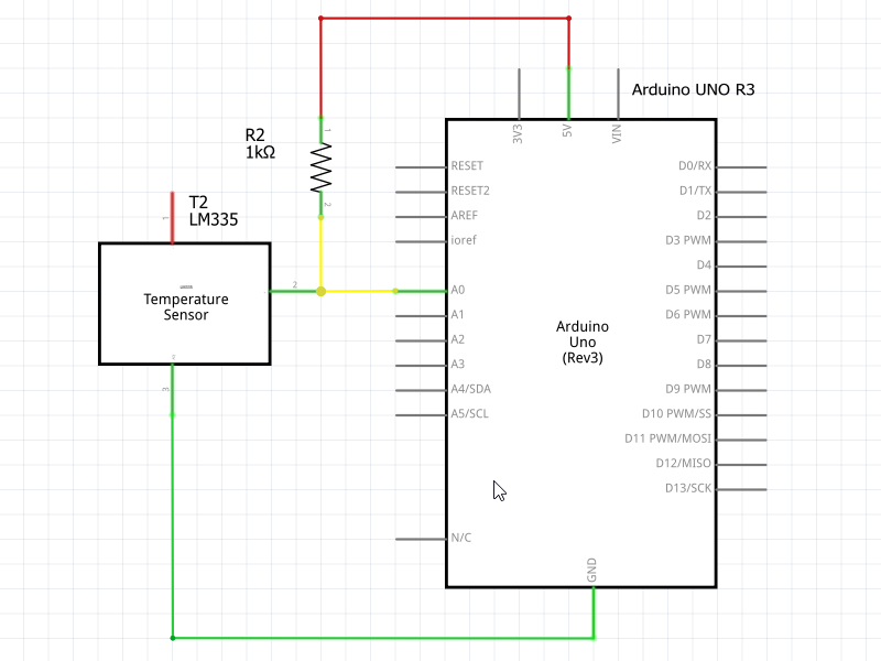
Once we have chosen a resistor R1 we have to connect the voltage divider to the Arduino as shown in the schematic. V0 of the voltage divider will be connected to the A0 pin of Arduino.
Programming
The below code will read the raw 10-bit ADC value at pin A0 / ADC0 / PC0 and further convert then into temperature and print it in the serial terminal.
/**
\file main.c
\brief Code to Read LM335 Temperature Sensor and Print in Serial Terminal

\verbatim

Created: 22-11-2020 03:20:10 PM
Author : Arnab Kumar Das
Website: www.ArnabKumarDas.com
Microcontroller Supported: ATmega48A/PA/88A/PA/168A/PA/328/P or Arduino UNO/NANO/MINI

Copyright (c) 2014-2020 Arnab Kumar Das
You may freely modify and share this code, as long as you keep this
notice intact (including the links above).
Licensed under the Creative Commons BY-SA 3.0 license:

  http://creativecommons.org/licenses/by-sa/3.0/

Disclaimer: To the extent permitted by law, Arnab Kumar Das provides this work
without any warranty.  It might be defective, in which case you agree
to be responsible for all resulting costs and damages.

                +-\/-+
          PC6  1|    |28  PC5 (A5/ADC5)
RXD  (D0) PD0  2|    |27  PC4 (A4/ADC4)
TXD  (D1) PD1  3|    |26  PC3 (A3/ADC3)
     (D2) PD2  4|    |25  PC2 (A2/ADC2)
PWM  (D3) PD3  5|    |24  PC1 (A1/ADC1)
XCK  (D4) PD4  6|    |23  PC0 (A0/ADC0)
          VCC  7|    |22  GND
          GND  8|    |21  AREF
          PB6  9|    |20  AVCC
          PB7 10|    |19  PB5 (D13)
OC0B (D5) PD5 11|    |18  PB4 (D12)
OC0A (D6) PD6 12|    |17  PB3 (D11) PWM
     (D7) PD7 13|    |16  PB2 (D10) PWM
     (D8) PB0 14|    |15  PB1 (D9)  PWM
                +----+

\endverbatim

*/

#include <avr/io.h>
#include "avr_adc.h"
#include "avr_usart.h"
#include <util/delay.h>


int main(void)
{
	/* ADC Configuration and Init */
	ADC_ConfigData ADC_Data;
	ADC_Data.Prescaler = ADC_PRESCALER_128;
	ADC_Data.VoltageReference = ADC_VOLTAGE_REFERENCE_AVCC;
	ADC_Init(ADC_Data);

	/* USART Configuration and Init */
	USART_ConfigData USART_Data;
	USART_Data.BaudRate = 9600;
	USART_Data.DataBit = USART_DATA_BIT_EIGHT;
	USART_Data.ParityBit = USART_PARITY_BIT_NO;
	USART_Data.StopBit = USART_STOP_BIT_ONE;
	USART_Data.UsartMode = USART_MODE_ASYNCHRONOUS;
	USART_Init(USART_Data);

	/* Local Variables */
	uint16_t ADC_RawData = 0x0000;
	float LM335_Temp = 0.0f;

    while (1)
    {
		/* Read ADC Value at Pin PC0 (A0/ADC0) */
		ADC_RawData = ADC_ReadPin(ADC0);

		/* Convert the raw ADC value to Temperature in Kelvin */
		LM335_Temp = ((float)( ADC_RawData * 5 ) / 1023) * 100;

		/* Convert the Temperature in Kelvin to Celsius */
		LM335_Temp = LM335_Temp - 273.15;

		/* Print the data in terminal */
		USART_TransmitString("\nLM335 Temperature Degree C = ");
		USART_WaitTillTransmitFree();
		USART_TransmitFloat(LM335_Temp,3);

		/* Wait for 500ms */
		_delay_ms(500);

    }
}
The first programming step is to initialize the ADC with the right Prescaler and voltage reference. The Prescaler selected for the ADC clock is 128 so ADC runs at 16MHz/128 = 125KHz. The temperature sensor / LM335 is connected to 5V, which is the max voltage Arduino / Atmega328p can handle as analog input, so the voltage reference for ADC conversion is set to AVCC / 5V.
	/* ADC Configuration and Init */
	ADC_ConfigData ADC_Data;
	ADC_Data.Prescaler = ADC_PRESCALER_128;
	ADC_Data.VoltageReference = ADC_VOLTAGE_REFERENCE_AVCC;
	ADC_Init(ADC_Data);
The second programming step is to initialize the USART to print out the required data. In this case, we will be printing the temperature data to the serial terminal. In the below configuration the USART is initialized to 9600baud, 8-bit, no parity, one stop bit configuration.
	/* USART Configuration and Init */
	USART_ConfigData USART_Data;
	USART_Data.BaudRate = 9600;
	USART_Data.DataBit = USART_DATA_BIT_EIGHT;
	USART_Data.ParityBit = USART_PARITY_BIT_NO;
	USART_Data.StopBit = USART_STOP_BIT_ONE;
	USART_Data.UsartMode = USART_MODE_ASYNCHRONOUS;
	USART_Init(USART_Data);
We also need two local variables to store the 10-bit ADC value and temperature.
	/* Local Variables */
	uint16_t ADC_RawData = 0x0000;
	float LM335_Temp = 0.0f;
The next step is to continuously ready the analog data at pin A0 and convert it to Kelvin temperature. The Kelvin temperature is further converted to Celsius temperature. Once we have the Celsius temperature we can then print it to the serial terminal using USART. This can run in an infinite loop every 500ms.
while (1)
{
    /* Read ADC Value at Pin PC0 (A0/ADC0) */
    ADC_RawData = ADC_ReadPin(ADC0);

    /* Convert the raw ADC value to Temperature in Kelvin */
    LM335_Temp = ((float)( ADC_RawData * 5 ) / 1023) * 100;

    /* Convert the Temperature in Kelvin to Celsius */
    LM335_Temp = LM335_Temp - 273.15;

    /* Print the data in terminal */
    USART_TransmitString("\nLM335 Temperature Degree C = ");
    USART_WaitTillTransmitFree();
    USART_TransmitFloat(LM335_Temp,3);

    /* Wait for 500ms */
    _delay_ms(500);
}
Execution
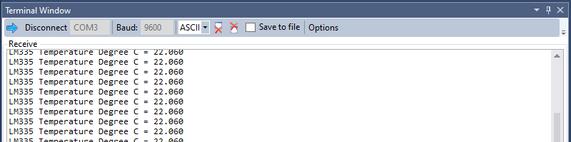
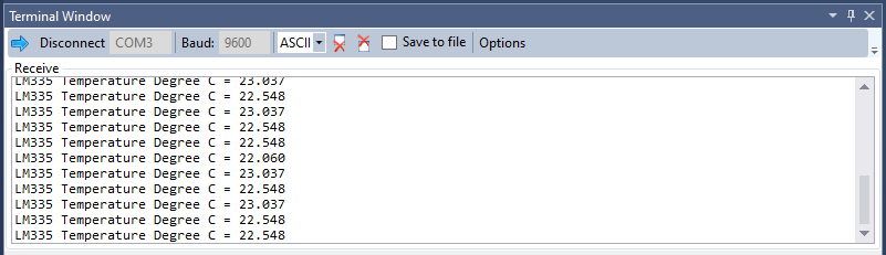
We have to connect the Arduino according to the schematic and program the Arduino. You can use Arduino’s serial programming, USB ASP, Atmel ICE, etc for flashing the Arduino. After the programming, we have to connect to the COM port of the Arduino and we will be able to see the output. The print should come every 500ms.
Conclusion
This tutorial teaches two very important concepts, one is how Zener based temperature sensor works and secondly interfacing LM335 with Arduino or Atmega328p microcontroller.
Scope of Improvement
- Using the calibrated mode of operation of LM335
- Using hardware and software filters to improve the quality of data


0 Comments