Note
This article is a part of Arduino / ATmega328p Embedded C Firmware Programming Tutorial. Consider exploring the course home page for articles on similar topics.

Arduino Tutorial Embedded C Register Level Arduino Master Class
Also visit the Release Page for Register Level Embedded C Hardware Abstraction Library and Code for AVR.
License
Copyright (c) 2014-2020 Arnab Kumar Das https://www.arnabkumardas.com/ You may freely modify and share this project and code, as long as you keep this notice intact (including the links). Licensed under the Creative Commons BY-SA 3.0 license:
http://creativecommons.org/licenses/by-sa/3.0/
Disclaimer: To the extent permitted by law, Arnab Kumar Das provides this work without any warranty. It might be defective, in which case you agree to be responsible for all resulting costs and damages.
Introduction
In this tutorial, we will learn how to interface a light sensor/photoresistor (LDR / Light Decreasing Resistance, or light-dependent resistor, or photo-conductive cell) with Arduino / Atmega328p. For this tutorial, we will be using ADC, USART, and GPIO hardware peripheral of the Arduino / Atmega328p. The concepts learned in this tutorial can also be applied to other projects involving ADC.
This tutorial has two parts. In the first part, we will understand how the LDR works, and in the second part, we will be controlling an LED connected to one GPIO pin based on the amount of light falling on the LDR.
The programming and code in this tutorial can be done in both Atmel Studio and Arduino IDE.
What You Will Learn
- How to Program and Interface LDR with Arduino?
- How to use LDR as Light Sensor with AVR ATmega328p?
- How to use ADC to read Light Intensity in Arduino/ATmega328p?
- How to Program ADC, UART and GPIO to interface Sensors in Arduino?
Prerequisite
Hardware Bill of Materials
- ATmega48A/PA/88A/PA/168A/PA/328/P or Arduino UNO/NANO/MINI
- USB ASP / Atmel ICE (if Arduino’s serial programming is not used)
- Dupont wire male to male
- Resistor 25K Ohms
- Breadboard
- LDR
Software Bill of Materials
- Atmel Studio / Arduino IDE
- Drivers
Hardware Description
LDR
A photoresistor / LDR is a passive component that decreases resistance with respect to receiving luminosity (light) on the component’s sensitive surface. The resistance of a photoresistor decreases with an increase in incident light intensity. The resistance varies in the range of Ω to MΩ and based on this LDRs can be used in different configurations to sense the light intensity and use that to control devices like street lights or perform a complex task.
Schematic Design
In this tutorial/experiment, we will be using the LDR in a voltage divider configuration where the variable resistance of the LDR will change the voltage drop distribution in the voltage divider and that can be further captured by the ADC.
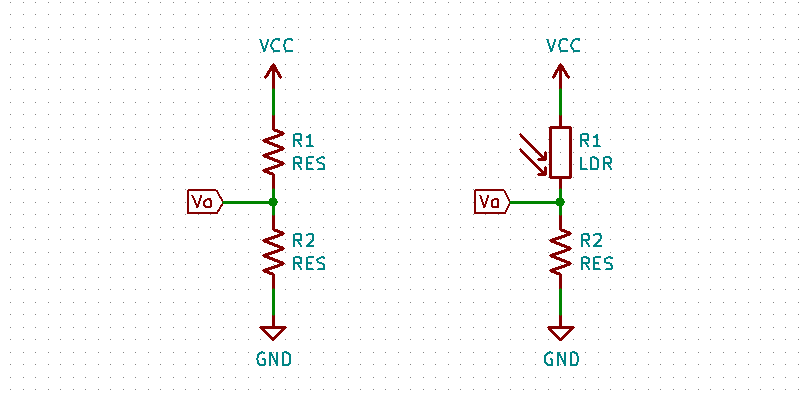
If we connect two resistors in series and give a voltage VCC to one end and GND to another ends there will be a current flowing I and the voltage drop at each resistor will be IR1 and IR2. The voltage at VO will be equal to IR2. The total voltage drop at both the resistor will be equal to VCC.

Based on the above formula voltage VO will vary if we keep R2 constant and change R1. In the case of R1 as LDR, the resistance will change when there is a change in light intensity and thus the voltage at VO will also change.
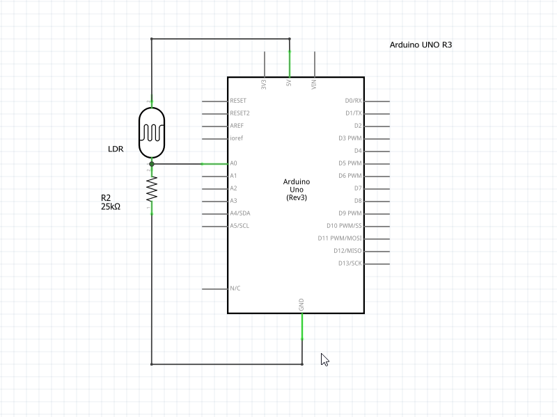
First, we will be connecting the LDR to a multimeter to know its resistance when no light falls on it. Mine was 27K so I choose resistor R2 of a value of 25K to keep the current flowing through the voltage divider low all the time. We will be using 5V for the VCC, so the maximum current that can flow through the voltage divider will be 0.0002A which will keep the power consumption low.
Once we have chosen a resistor R2 we have to connect the voltage divider to the Arduino as shown in the schematic. V0 of the voltage divider will be connected to the A0 pin of Arduino.
Part 1: Reading Analog Voltage VO of the Voltage Divider on Serial Terminal using ADC and USART
Programming
The below code will read the raw 10-bit ADC value at pin A0 / ADC0 / PC0 and further convert them into voltage and print it in the serial terminal.
/**
\file main.c
\brief Code to Read Analog Data from ADC and Print in Serial Terminal

\verbatim

Created: 22-11-2020 03:20:10 PM
Author : Arnab Kumar Das
Website: www.ArnabKumarDas.com
Microcontroller Supported: ATmega48A/PA/88A/PA/168A/PA/328/P or Arduino UNO/NANO/MINI

Copyright (c) 2014-2020 Arnab Kumar Das
You may freely modify and share this code, as long as you keep this
notice intact (including the links above).
Licensed under the Creative Commons BY-SA 3.0 license:

  http://creativecommons.org/licenses/by-sa/3.0/

Disclaimer: To the extent permitted by law, Arnab Kumar Das provides this work
without any warranty.  It might be defective, in which case you agree
to be responsible for all resulting costs and damages.

                +-\/-+
          PC6  1|    |28  PC5 (A5/ADC5)
RXD  (D0) PD0  2|    |27  PC4 (A4/ADC4)
TXD  (D1) PD1  3|    |26  PC3 (A3/ADC3)
     (D2) PD2  4|    |25  PC2 (A2/ADC2)
PWM  (D3) PD3  5|    |24  PC1 (A1/ADC1)
XCK  (D4) PD4  6|    |23  PC0 (A0/ADC0)
          VCC  7|    |22  GND
          GND  8|    |21  AREF
          PB6  9|    |20  AVCC
          PB7 10|    |19  PB5 (D13)
OC0B (D5) PD5 11|    |18  PB4 (D12)
OC0A (D6) PD6 12|    |17  PB3 (D11) PWM
     (D7) PD7 13|    |16  PB2 (D10) PWM
     (D8) PB0 14|    |15  PB1 (D9)  PWM
                +----+

\endverbatim

*/

#include <avr/io.h>
#include "avr_adc.h"
#include "avr_usart.h"
#include <util/delay.h>


int main(void)
{
	/* ADC Configuration and Init */
	ADC_ConfigData ADC_Data;
	ADC_Data.Prescaler = ADC_PRESCALER_128;
	ADC_Data.VoltageReference = ADC_VOLTAGE_REFERENCE_AVCC;
	ADC_Init(ADC_Data);

	/* USART Configuration and Init */
	USART_ConfigData USART_Data;
	USART_Data.BaudRate = 9600;
	USART_Data.DataBit = USART_DATA_BIT_EIGHT;
	USART_Data.ParityBit = USART_PARITY_BIT_NO;
	USART_Data.StopBit = USART_STOP_BIT_ONE;
	USART_Data.UsartMode = USART_MODE_ASYNCHRONOUS;
	USART_Init(USART_Data);

	/* Local Variables */
	uint16_t ADC_RawData = 0x0000;
	float ADC_Voltage = 0.0f;

    while (1)
    {
		/* Read ADC Value at Pin PC0 (A0/ADC0) */
		ADC_RawData = ADC_ReadPin(ADC0);

		/* Convert the raw ADC value to Voltage */
		ADC_Voltage = (float)( ADC_RawData * 5 ) / 1023;

		/* Print the data in terminal */
		USART_TransmitString("\nVoltage at ADC0 Pin = ");
		USART_WaitTillTransmitFree();
		USART_TransmitFloat(ADC_Voltage,3);

		/* Wait for 500ms */
		_delay_ms(500);
    }
}
The first programming step is to initialize the ADC with the right Prescaler and voltage reference. The Prescaler selected for the ADC clock is 128 so ADC runs at 16MHz/128 = 125KHz. The voltage divider is connected to 5V, which is the max voltage Arduino / Atmega328p can handle as analog input, so the voltage reference for ADC conversion is set to AVCC / 5V.
	/* ADC Configuration and Init */
	ADC_ConfigData ADC_Data;
	ADC_Data.Prescaler = ADC_PRESCALER_128;
	ADC_Data.VoltageReference = ADC_VOLTAGE_REFERENCE_AVCC;
	ADC_Init(ADC_Data);
The second programming step is to initialize the USART to print out the required data. In this case, we will be printing the ADC data. In the below configuration the USART is initialized to 9600baud, 8-bit, no parity, one stop bit configuration.
	/* USART Configuration and Init */
	USART_ConfigData USART_Data;
	USART_Data.BaudRate = 9600;
	USART_Data.DataBit = USART_DATA_BIT_EIGHT;
	USART_Data.ParityBit = USART_PARITY_BIT_NO;
	USART_Data.StopBit = USART_STOP_BIT_ONE;
	USART_Data.UsartMode = USART_MODE_ASYNCHRONOUS;
	USART_Init(USART_Data);
We also need two local variables to store the 10-bit ADC value and analog voltage.
	/* Local Variables */
	uint16_t ADC_RawData = 0x0000;
	float ADC_Voltage = 0.0f;
The next step is to continuously ready the analog value at pin A0 and convert it to voltage. Once we have the voltage we can then print it to the serial terminal using USART. This can run in an infinite loop every 500ms.
     while (1)
    {
		/* Read ADC Value at Pin PC0 (A0/ADC0) */
		ADC_RawData = ADC_ReadPin(ADC0);

		/* Convert the raw ADC value to Voltage */
		ADC_Voltage = (float)( ADC_RawData * 5 ) / 1023;

		/* Print the data in terminal */
		USART_TransmitString("\nVoltage at ADC0 Pin = ");
		USART_WaitTillTransmitFree();
		USART_TransmitFloat(ADC_Voltage,3);

		/* Wait for 500ms */
		_delay_ms(500);
    }
Execution
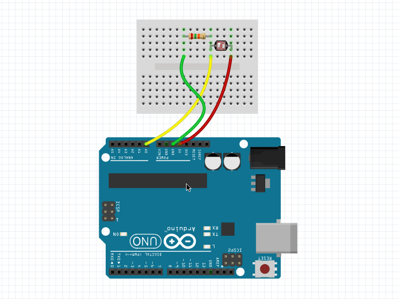
We have to connect the Arduino according to the schematic and program the Arduino. You can use Arduino’s serial programming, USB ASP, Atmel ICE, etc for flashing the Arduino. After the programming, we have to connect to the COM port of the Arduino and we will be able to see the output. The print should come every 500ms.
If you change the light intensity you should be able to see similar output as shown below.

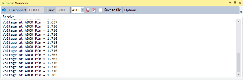

Conclusion
Part 1 of the tutorial helped in understanding the relation of light intensity to the output voltage of the voltage divider. We also learned how an LDR works as a light sensor.
Part 2: Using LDR as Light Sensor and Controlling a LED using ADC and GPIO
Programming
The below code will read the voltage divider output and switch on a LED when it is dark below a threshold.
/**
\file main.c
\brief Code to Read Light Sensor / LDR value and Switch on a LED when it is Dark

\verbatim

Created: 22-11-2020 04:45:10 PM
Author : Arnab Kumar Das
Website: www.ArnabKumarDas.com
Microcontroller Supported: ATmega48A/PA/88A/PA/168A/PA/328/P or Arduino UNO/NANO/MINI

Copyright (c) 2014-2020 Arnab Kumar Das
You may freely modify and share this code, as long as you keep this
notice intact (including the links above).
Licensed under the Creative Commons BY-SA 3.0 license:

  http://creativecommons.org/licenses/by-sa/3.0/

Disclaimer: To the extent permitted by law, Arnab Kumar Das provides this work
without any warranty.  It might be defective, in which case you agree
to be responsible for all resulting costs and damages.

                +-\/-+
          PC6  1|    |28  PC5 (A5/ADC5)
RXD  (D0) PD0  2|    |27  PC4 (A4/ADC4)
TXD  (D1) PD1  3|    |26  PC3 (A3/ADC3)
     (D2) PD2  4|    |25  PC2 (A2/ADC2)
PWM  (D3) PD3  5|    |24  PC1 (A1/ADC1)
XCK  (D4) PD4  6|    |23  PC0 (A0/ADC0)
          VCC  7|    |22  GND
          GND  8|    |21  AREF
          PB6  9|    |20  AVCC
          PB7 10|    |19  PB5 (D13)
OC0B (D5) PD5 11|    |18  PB4 (D12)
OC0A (D6) PD6 12|    |17  PB3 (D11) PWM
     (D7) PD7 13|    |16  PB2 (D10) PWM
     (D8) PB0 14|    |15  PB1 (D9)  PWM
                +----+

\endverbatim

*/

#include <avr/io.h>
#include "avr_gpio.h"
#include "avr_adc.h"


int main(void)
{
	/* ADC Configuration and Init */
	ADC_ConfigData ADC_Data;
	ADC_Data.Prescaler = ADC_PRESCALER_128;
	ADC_Data.VoltageReference = ADC_VOLTAGE_REFERENCE_AVCC;
	ADC_Init(ADC_Data);

	/* GPIO Pin PB5 (D13) Configuration and Init */
	GPIO_InitPin(13,GPIO_MODE_OUTPUT);

	/* Local Variables */
	uint16_t ADC_RawData = 0x0000;

	while (1)
	{
		/* Read ADC Value at Pin PC0 (A0/ADC0) */
		ADC_RawData = ADC_ReadPin(ADC0);

		if (ADC_RawData < 400)
		{
			GPIO_WritePinHigh(13);
		}
		else
		{
			GPIO_WritePinLow(13);
		}

	}
}
The first programming step is to initialize the ADC with the right Prescaler and voltage reference. The Prescaler selected for the ADC clock is 128 so ADC runs at 16MHz/128 = 125KHz. We are connecting the voltage divider to 5V, which is the max voltage Arduino / Atmega328p can handle as analog input. So we selected the voltage reference for ADC conversion as AVCC / 5V.
	/* ADC Configuration and Init */
	ADC_ConfigData ADC_Data;
	ADC_Data.Prescaler = ADC_PRESCALER_128;
	ADC_Data.VoltageReference = ADC_VOLTAGE_REFERENCE_AVCC;
	ADC_Init(ADC_Data);
In the second step, the GPIO pin PB5 / D13 is initialized as an output pin.
	/* GPIO Pin PB5 (D13) Configuration and Init */
	GPIO_InitPin(13,GPIO_MODE_OUTPUT);
We also need a local variable to store the 10-bit ADC value.
	/* Local Variables */
	uint16_t ADC_RawData = 0x0000;
In the last step in an infinite loop, we read the ADC output at pin A0, and if the value is less than 400 we write the GPIO pin D13 on Arduino HIGH which turns the onboard LED. If the light intensity increases and the ADC value is more than 400 then the LED turns off or the pin goes LOW.
	while (1)
	{
		/* Read ADC Value at Pin PC0 (A0/ADC0) */
		ADC_RawData = ADC_ReadPin(ADC0);

		if (ADC_RawData < 400)
		{
			GPIO_WritePinHigh(13);
		}
		else
		{
			GPIO_WritePinLow(13);
		}

	}
Execution
We have to connect the Arduino according to the schematic and program the Arduino. You can use Arduino’s serial programming, USB ASP, Atmel ICE, etc for flashing the Arduino. After the programming, we have to vary the light intensity falling on the LDR and monitor the onboard LED at pin D13. When the light intensity goes low the LED should switch on.
Conclusion
Part 2 of the tutorial helped in using an environmental parameter to control a device. We were able to use the light intensity falling on the light sensor / LDR to decide if the LED need to be on. This knowledge of sensing and control can be used in complex projects and applications.


5 Comments
filmi full izle · January 17, 2021 at 5:25 am
You have observed very interesting points! ps decent site. Dory Noll Tiffany
Crazy Engineer · January 18, 2021 at 2:39 pm
Thank you for spending time on the website. Hopefully, this article has helped you.
Ankit Dobariya · January 22, 2021 at 6:23 pm
pls give the avr_adc.h and avr_usart.h code.
pls pls…..
Crazy Engineer · January 23, 2021 at 11:24 pm
The attachments are available on the same page with all the code and header files.
acv888 · January 27, 2023 at 8:49 pm
I’m working on a project to control the colors on a TFT-Display via lux values and this helped me immensely. Thank you very much for your effort.