Embedded Controller Or General-Purpose Computer?
Objectives and Prerequisites
Section titled “Objectives and Prerequisites”Compare an embedded system with a general-purpose computer by asking what job it serves, what resources it must fit, how it interacts with the physical world and how it is maintained. Read the embedded-system lesson first.
Compare the Design Goals
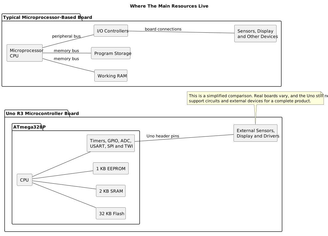
Section titled “Compare the Design Goals”| Question | Embedded controller | General-purpose computer |
|---|---|---|
| Main goal | Perform a defined product function reliably | Run a wide range of applications selected by users |
| Hardware | Chosen for required signals, cost, size and environment | Chosen for broad compatibility, user interaction and performance |
| Software | Often organized around fixed control tasks | Often includes an operating system and application environment |
| Inputs and outputs | Sensors, switches, motors, relays, serial buses | Keyboard, display, storage and network interfaces, with physical I/O added as needed |
| Resources | May have strict Flash, SRAM, power and timing budgets | Usually has more memory and storage, though budgets still exist |
| Timing | Response deadlines may be part of product behavior | Timing may be less visible to users, but can also be critical |
| Maintenance | Updates can be tightly controlled and hardware-specific | Users commonly install and update software and peripherals |
This is a useful comparison, not a definition that every product must fit exactly. A modern embedded system may run a large operating system and network services. A general-purpose computer can run real-time software or control industrial machinery. The distinction comes from the system’s purpose, integration and constraints, not only its CPU or operating system.
Worked Comparison: Kitchen Timer and Desktop Application
Section titled “Worked Comparison: Kitchen Timer and Desktop Application”A simple kitchen timer needs a clock, a start button, a display or buzzer and a way to keep time while the user does something else. A small microcontroller can perform this fixed task with low power and a few components. It must respond to button input, count elapsed time and signal when the interval expires.
A desktop timer application can offer multiple timers, themes, history, network synchronization and accessibility controls because it shares a general-purpose computer’s display, storage and operating system. It also depends on that computer being powered on, the application being available and operating-system scheduling. Neither implementation is automatically better; the required product determines the trade-off.
For the Uno version, the button lab demonstrates an input and output path. A complete timer would additionally require a time base, state management, a display or buzzer and tests for rollover and reset behavior. The Uno is a teaching platform for these ideas, not a finished consumer appliance.
Use Constraints to Choose Architecture
Section titled “Use Constraints to Choose Architecture”Ask concrete questions before choosing the processor or programming model:
- What event must be detected, and how soon must the system respond?
- Which signals and loads need hardware interfaces?
- What happens if power is interrupted or a sensor wire disconnects?
- How much energy, size, heat and cost can the product use?
- Does the software need network access, a filesystem or a user interface?
- How will it be tested and safely updated after delivery?
The answers determine whether a small bare-metal controller, a larger embedded computer or a general-purpose computer is suitable. A small chip is not a virtue by itself; it is useful when it meets the product requirements with enough margin and can be maintained.
Exercise with Answer
Section titled “Exercise with Answer”A device reads a temperature sensor every second and switches a fan when a threshold is crossed. Is it embedded only because it uses a microcontroller?
Answer: no. It is embedded because it is integrated into a product or process for a defined control job, with physical inputs, outputs and timing/resource requirements. A computer with a sensor interface could implement the same job and would still be part of an embedded control system if integrated that way.
Code Walkthrough
Section titled “Code Walkthrough”Example code on GitHub:
Debounced push button
Section titled “Debounced push button”The example’s main() configures its peripherals, runs the algorithm and reports or displays the result. These source operations are listed in execution order:
avr_debounce_t button;- Use the linked public header for this function’s parameters, register ownership, blocking behavior and status values.bool level = true;- Stores this intermediate or output value for the next algorithm step. Check the units and range represented by each operand.bool led = false;- Stores this intermediate or output value for the next algorithm step. Check the units and range represented by each operand.(void)avr_gpio_mode(2U, AVR_GPIO_INPUT_PULLUP);- Maps the Uno header pin to its AVR port, sets its DDR direction bit and prepares the PORT latch for the requested initial level or pull-up.(void)avr_gpio_mode(13U, AVR_GPIO_OUTPUT);- Maps the Uno header pin to its AVR port, sets its DDR direction bit and prepares the PORT latch for the requested initial level or pull-up.avr_tick_init();- Configures the course millisecond tick interrupt source; it does not enable global interrupts itself.avr_debounce_init(&button, true, 0UL);- Seeds the stable/candidate input state and timestamp so the next transition is timed consistently.sei();- Enables global interrupts after the example has configured its sources and shared state.for (;;)- Repeats the foreground task indefinitely; each pass checks inputs, advances the calculation or services the peripheral shown below.(void)avr_gpio_read(2U, &level);- Reads the electrical level through PINx without changing direction or the output latch.if (avr_debounce_update(&button, level, avr_tick_ms(), 20U) && !button.stable)- This condition chooses the next path based on the API result. Accepts a changed input only after it remains stable for the requested interval, then reports that accepted change once.led = !led;- Stores this intermediate or output value for the next algorithm step. Check the units and range represented by each operand.(void)avr_gpio_write(13U, led);- Changes the pin’s PORT output latch; for an input pin this selects its pull-up state.
Algorithm: A candidate input must remain unchanged for 20 ms before becoming stable. No delay occurs inside an ISR. Expected behaviour: Each press toggles L once; holding the button does not repeat HAL source files in this repository: ATmega328P HAL on GitHub
include/avr_hal/gpio.hinclude/avr_hal/tick.hlib/drivers/debounce.clib/drivers/debounce.hlib/interrupts/tick.csrc/gpio.c
HAL Software Self-Test
Section titled “HAL Software Self-Test”The example’s main() configures its peripherals, runs the algorithm and reports or displays the result. These source operations are listed in execution order:
avr_debounce_t button;- Use the linked public header for this function’s parameters, register ownership, blocking behavior and status values.uint8_t result = 0U;- Clears the state/counter after its threshold is reached so the next interval starts from zero.(void)avr_uart_init(9600UL);- Configures USART0 for asynchronous 8N1. It chooses a baud divisor and normal/double-speed mode, programs UBRR0/UCSR0A/UCSR0C, then enables receive and transmit in UCSR0B.CHECK(avr_gpio_mode(20U, AVR_GPIO_OUTPUT) == AVR_ERROR_ARGUMENT);- Maps the Uno header pin to its AVR port, sets its DDR direction bit and prepares the PORT latch for the requested initial level or pull-up.CHECK(avr_gpio_read(13U, NULL) == AVR_ERROR_ARGUMENT);- Reads the electrical level through PINx without changing direction or the output latch.CHECK(avr_timer_ctc(AVR_TIMER0, 32U, 100U) == AVR_ERROR_ARGUMENT);- Configures 0 in CTC mode with prescaler 32 and OCRnA TOP 100; event rate is 16 MHz / (32 x (100 + 1)) = 4950.5 Hz. The HAL disables this timer’s interrupt sources and leaves flag polling to the caller.CHECK(avr_timer_ctc(AVR_TIMER0, 64U, 256U) == AVR_ERROR_ARGUMENT);- Configures 0 in CTC mode with prescaler 64 and OCRnA TOP 256; event rate is 16 MHz / (64 x (256 + 1)) = 972.763 Hz. The HAL disables this timer’s interrupt sources and leaves flag polling to the caller.CHECK(avr_timer_ctc(AVR_TIMER2, 128U, 124U) == AVR_OK);- Configures 2 in CTC mode with prescaler 128 and OCRnA TOP 124; event rate is 16 MHz / (128 x (124 + 1)) = 1000 Hz. The HAL disables this timer’s interrupt sources and leaves flag polling to the caller.CHECK((TCCR2B & 7U) == 5U);- Selects Timer2 clock/prescaler and remaining waveform bits. Timer2 has distinct prescaler encodings.CHECK(avr_timer1_pwm(8U, 40000U, 3000U) == AVR_OK);- Configures Timer1 mode 14 with prescaler 8; ICR1 becomes 39999, giving a 20 ms frame, and OCR1A starts at 3000 ticks (1500 us high).CHECK(ICR1 == 39999U && OCR1A == 3000U);- Timer1 input-capture register and, in the selected PWM mode, the TOP value. Timer1 Compare A; it sets the match point or PWM pulse width.CHECK(avr_adc_millivolts(512U, 5000U) == 2500U);- Callsavr_adc_millivolts(); its public HAL header defines the arguments, register ownership, blocking behavior and status results.CHECK(avr_adc_read(6U, NULL, 0U) == AVR_ERROR_ARGUMENT);- Callsavr_adc_read(); its public HAL header defines the arguments, register ownership, blocking behavior and status results.CHECK(avr_eeprom_read(1024U, &result, 0UL) == AVR_ERROR_ARGUMENT);- Callsavr_eeprom_read(); its public HAL header defines the arguments, register ownership, blocking behavior and status results.CHECK(avr_twi_transfer(0U, NULL, 0U, NULL, 0U, 0UL) == AVR_ERROR_ARGUMENT);- Callsavr_twi_transfer(); its public HAL header defines the arguments, register ownership, blocking behavior and status results.CHECK(avr_elapsed(5UL, UINT32_MAX - 4UL, 10UL));- Callsavr_elapsed(); its public HAL header defines the arguments, register ownership, blocking behavior and status results.CHECK(!avr_elapsed(5UL, UINT32_MAX - 4UL, 11UL));- Callsavr_elapsed(); its public HAL header defines the arguments, register ownership, blocking behavior and status results.avr_debounce_init(&button, true, UINT32_MAX - 10UL);- Callsavr_debounce_init(); its public HAL header defines the arguments, register ownership, blocking behavior and status results.CHECK(!avr_debounce_update(&button, false, UINT32_MAX - 9UL, 20U));- Callsavr_debounce_update(); its public HAL header defines the arguments, register ownership, blocking behavior and status results.CHECK(!avr_debounce_update(&button, false, 9UL, 20U));- Callsavr_debounce_update(); its public HAL header defines the arguments, register ownership, blocking behavior and status results.CHECK(avr_debounce_update(&button, false, 10UL, 20U));- Accepts a changed input only after it remains stable for the requested interval, then reports that accepted change once.CHECK(!avr_debounce_update(&button, false, 11UL, 20U));- Accepts a changed input only after it remains stable for the requested interval, then reports that accepted change once.(void)avr_uart_write((const uint8_t *)"PASS\n", 5U, AVR_POLL_BUDGET);- Sends the specified bytes through USART0; a timeout can occur after a prefix has already been sent.for (;;)- Repeats the foreground task indefinitely; each pass checks inputs, advances the calculation or services the peripheral shown below.
Algorithm: A bounded self-test checks software contracts and links a second source file so header-owned definitions are detected. Expected behaviour: The fixture prints PASS after argument, timer-range, debounce and independent-translation-unit checks; otherwise it prints FAIL and stops HAL source files in this repository: ATmega328P HAL on GitHub
include/avr_hal/adc.hinclude/avr_hal/common.hinclude/avr_hal/eeprom.hinclude/avr_hal/gpio.hinclude/avr_hal/timer.hinclude/avr_hal/twi.hinclude/avr_hal/uart.hlib/drivers/debounce.clib/drivers/debounce.hsrc/adc.csrc/common.csrc/eeprom.csrc/gpio.csrc/timer.csrc/twi.csrc/uart.c
References
Section titled “References”Use the course’s ATmega328P specification, clock and testing lessons to examine the Uno resource limits, timing assumptions and validation methods. Product architecture depends on the full system requirements, not a processor feature list alone.