GPIO Concepts
Objectives and Prerequisites
Section titled “Objectives and Prerequisites”General-purpose input/output (GPIO) pins connect firmware to digital signals. In this lesson, you will distinguish an input from an output, explain why an unconnected input can behave unpredictably, and identify when a driver circuit is needed. Review the equipment and safe-circuit notes before connecting external circuits.
A Digital Pin Measures Voltage
Section titled “A Digital Pin Measures Voltage”A digital input reports whether its voltage is interpreted as logic low or logic high. It does not receive a C true or false value directly. The device has input thresholds, and voltages in the transition region may not have a reliable logic interpretation. For an Uno R3, use the board’s 5 V logic only with components whose data sheets permit those levels.
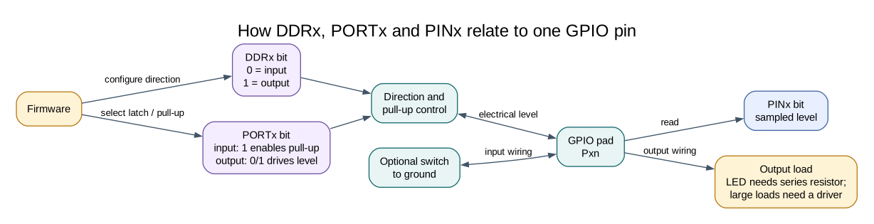
An input left unconnected is floating. It has no firm connection to a high or low level, so noise or nearby circuits can change the reading. A pull-up resistor connects the input weakly to the supply; a pull-down connects it weakly to ground. The ATmega328P can enable internal pull-ups on GPIO inputs.
Active-Low Inputs
Section titled “Active-Low Inputs”The common button circuit connects D2 to ground when pressed and enables the internal pull-up. Released reads high; pressed reads low. This is called active-low because the action is represented by a low electrical level.
| Button state | D2 connection | Pin reading |
|---|---|---|
| Released | Pull-up holds input high | Logic high |
| Pressed | Switch connects input to ground | Logic low |
An active-low signal is not an error. It is a circuit choice. Firmware should name the state clearly and avoid assuming that “pressed” always means a one bit.
A Pin Is Not a Power Supply
Section titled “A Pin Is Not a Power Supply”An output pin creates a logic signal within the device’s electrical limits. It is not a general-purpose power source. An LED needs a series resistor, and motors, relay coils and other larger loads need a suitable driver and protection circuit. Check the absolute maximum ratings and recommended operating conditions in the datasheet; do not treat absolute maximum values as normal design targets.
Exercise with Answer
Section titled “Exercise with Answer”Why can an unconnected input sometimes read high and sometimes low?
Answer: The pin has no defined voltage source. Electrical noise and coupling can move its voltage across the input threshold. Add a suitable pull-up or pull-down, or connect it to a circuit that defines the level.
Code Walkthrough
Section titled “Code Walkthrough”Example code on GitHub:
Register-level Blink
Section titled “Register-level Blink”The example’s main() configures its peripherals, runs the algorithm and reports or displays the result. These source operations are listed in execution order:
PORTB &= (uint8_t)~_BV(PORTB5);- Sets or clears the Port B output latch. When the pin is an output, this determines its output level; on an input, it controls the pull-up.DDRB |= _BV(DDB5);- Sets the Port B direction bits; a set bit selects output mode.for (;;)- Repeats the foreground task indefinitely; each pass checks inputs, advances the calculation or services the peripheral shown below.PINB = _BV(PINB5);- Writing a one to a PINB bit toggles that pin’s PORTB output latch on the ATmega328P._delay_ms(500);- Waits for the stated interval; the foreground does no other work during this blocking delay.
Algorithm: Pin direction and output latch are separate hardware state. Expected behaviour: L toggles every 500 ms HAL source files in this repository: ATmega328P HAL on GitHub
Debounced push button
Section titled “Debounced push button”The example’s main() configures its peripherals, runs the algorithm and reports or displays the result. These source operations are listed in execution order:
avr_debounce_t button;- Use the linked public header for this function’s parameters, register ownership, blocking behavior and status values.bool level = true;- Stores this intermediate or output value for the next algorithm step. Check the units and range represented by each operand.bool led = false;- Stores this intermediate or output value for the next algorithm step. Check the units and range represented by each operand.(void)avr_gpio_mode(2U, AVR_GPIO_INPUT_PULLUP);- Maps the Uno header pin to its AVR port, sets its DDR direction bit and prepares the PORT latch for the requested initial level or pull-up.(void)avr_gpio_mode(13U, AVR_GPIO_OUTPUT);- Maps the Uno header pin to its AVR port, sets its DDR direction bit and prepares the PORT latch for the requested initial level or pull-up.avr_tick_init();- Configures the course millisecond tick interrupt source; it does not enable global interrupts itself.avr_debounce_init(&button, true, 0UL);- Seeds the stable/candidate input state and timestamp so the next transition is timed consistently.sei();- Enables global interrupts after the example has configured its sources and shared state.for (;;)- Repeats the foreground task indefinitely; each pass checks inputs, advances the calculation or services the peripheral shown below.(void)avr_gpio_read(2U, &level);- Reads the electrical level through PINx without changing direction or the output latch.if (avr_debounce_update(&button, level, avr_tick_ms(), 20U) && !button.stable)- This condition chooses the next path based on the API result. Accepts a changed input only after it remains stable for the requested interval, then reports that accepted change once.led = !led;- Stores this intermediate or output value for the next algorithm step. Check the units and range represented by each operand.(void)avr_gpio_write(13U, led);- Changes the pin’s PORT output latch; for an input pin this selects its pull-up state.
Algorithm: A candidate input must remain unchanged for 20 ms before becoming stable. No delay occurs inside an ISR. Expected behaviour: Each press toggles L once; holding the button does not repeat HAL source files in this repository: ATmega328P HAL on GitHub
include/avr_hal/gpio.hinclude/avr_hal/tick.hlib/drivers/debounce.clib/drivers/debounce.hlib/interrupts/tick.csrc/gpio.c
References
Section titled “References”- ATmega328P product page and datasheet, digital input/output electrical characteristics.
- Uno R3 pinout
- GPIO registers
- Button and safe-load wiring