SN74HC595 Serial-In Shift Register

What You Will Learn
Section titled “What You Will Learn”The SN74HC595 shifts serial bits into an internal register. A separate storage latch copies all eight bits to its output pins together. The Uno can therefore change a group of outputs after the complete byte has arrived. The 595 adds outputs; it does not read input signals.
Parts and Wiring
Section titled “Parts and Wiring”Use one 74HC595, eight LEDs, one current-limiting resistor per LED and a 100 nF bypass capacitor close to the IC. Check the pinout for your package before wiring.
| Uno R3 | 74HC595 signal | Purpose |
|---|---|---|
| D2 | SER / DS | Serial data |
| D3 | SRCLK / SHCP | Shift-register clock |
| D4 | RCLK / STCP | Storage-latch clock |
| 5 V | VCC | Supply |
| GND | GND | Shared reference |
| GND | OE low | Enable outputs; active-low control |
| 5 V | SRCLR high | Keep active-low shift-register clear inactive |
| QA–QH | Each through 2.2 kΩ resistor to LED, then GND | Eight visible outputs |
At 5 V, the selected 74HC logic input thresholds suit the Uno’s 5 V outputs. Follow the part datasheet’s output-current and aggregate package-current limits. Do not treat the chip as eight unrestricted LED drivers.
Shift and Latch Sequence
Section titled “Shift and Latch Sequence”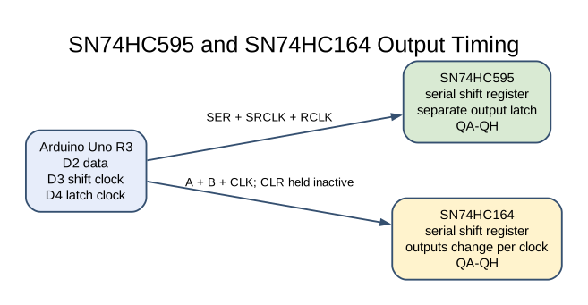
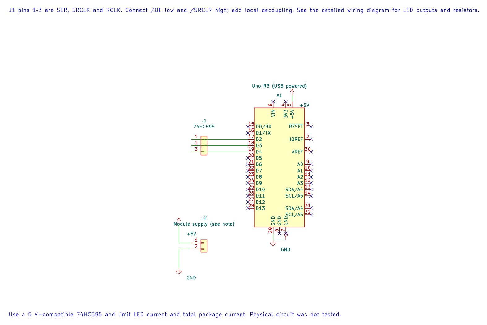
The editable KiCad connection sheet records the Uno signal and supply pins. The package control pins, output resistors and LEDs are described in the wiring table and should be connected as shown there.
For each bit, Lab 29 sets D2, pulses D3 high and then low. After all eight bits are shifted, it pulses D4. Only that latch edge updates QA–QH, so intermediate shift-register values are not shown on the LEDs.
The example sends a walking-one pattern, one bit at a time. When 0x01 is sent least-significant bit first, QA becomes high after the latch. Then 0x02 lights the next output, continuing through the byte. Exact LED order depends on the package output wiring.
Build and Try the Lab
Section titled “Build and Try the Lab”python atmega328p-labs/tools/build.py 29-shift-595 --compiler gccpython atmega328p-labs/tools/build.py 29-shift-595 --compiler xc8After wiring and uploading through the serial bootloader, observe that the LEDs change together at the latch pulse. Change the walking-one value to walking-zero and note the visible sequence. Only add a second cascaded 595 after the first is behaving correctly.
Code Walkthrough
Section titled “Code Walkthrough”SN74HC595 shift and latch
Section titled “SN74HC595 shift and latch”The example’s main() configures its peripherals, runs the algorithm and reports or displays the result. These source operations are listed in execution order:
for (uint8_t pin = 2U; pin < 5U; ++pin)- Repeats whilepin < 5Uis true;uint8_t pin = 2Usets the starting state and++pinadvances it each pass.(void)avr_gpio_mode(pin, AVR_GPIO_OUTPUT);- Maps the Uno header pin to its AVR port, sets its DDR direction bit and prepares the PORT latch for the requested initial level or pull-up.for (;;)- Repeats the foreground task indefinitely; each pass checks inputs, advances the calculation or services the peripheral shown below.for (uint8_t b = 0U; b < 8U; ++b)- Repeats whileb < 8Uis true;uint8_t b = 0Usets the starting state and++badvances it each pass._delay_ms(150);- Waits for the stated interval; the foreground does no other work during this blocking delay.
Algorithm: The shift register changes internally during clocks; a separate latch edge updates outputs together. Respect aggregate package current limits, not just each output rating. Expected behaviour: One LED advances across eight latched outputs HAL source files in this repository: ATmega328P HAL on GitHub
Common Problems
Section titled “Common Problems”- No LEDs light: Check VCC/GND, OE low, SRCLR high and each LED’s polarity.
- The wrong order lights: Check whether your code shifts most-significant or least-significant bit first and trace the output wiring.
- Outputs change during shifting: Check that the latch pin is D4 and is pulsed only after all eight data bits.
- The IC or LEDs get warm: Increase resistor values and review per-pin and total-current ratings.
Check Your Understanding
Section titled “Check Your Understanding”- Why does the 595 have separate shift and storage registers?
- What does OE do when it is high?
- Does the 595 provide eight extra input pins?
Suggested answers: The storage register hides intermediate bits and updates the outputs together. OE high disables the tri-state outputs. No; this device is an output expander and does not read inputs.