Interfacing A Seven-Segment Display
Objectives and Prerequisites
Section titled “Objectives and Prerequisites”A seven-segment display is seven LEDs arranged to form digits. This lab uses a common-cathode single-digit display and GPIO pins D2 through D8. Read GPIO programming and binary masks first.
Parts and Wiring
Section titled “Parts and Wiring”Use a common-cathode display, seven 1 kΩ resistors and jumper wires. Follow the package data sheet to identify the segment pins; segment letters are not package pin numbers.
| Uno connection | Display connection |
|---|---|
| D2 through D8, each through its own 1 kΩ resistor | Segments a through g, in order |
| GND | Common-cathode pin or pins |
| Not connected | Decimal point |
The resistor belongs in series with each segment. The display package may have two common pins; confirm their function in its pin diagram. Never assume the segment order from the physical pin layout.
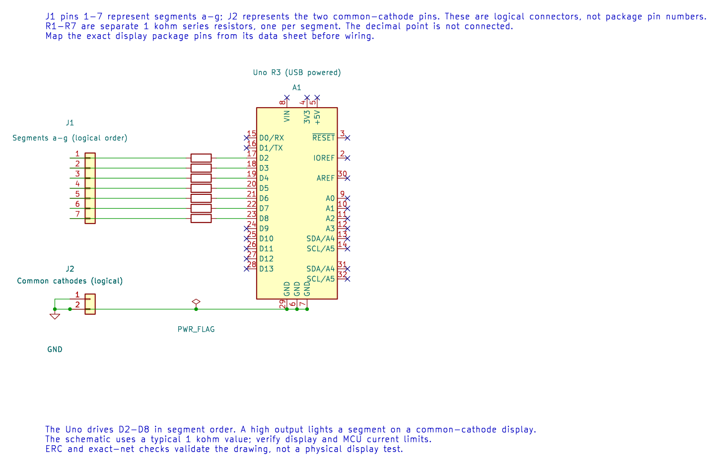
The editable KiCad schematic uses logical connectors: J1 pins 1-7 are segments a-g, and J2 represents the common-cathode pins. They are not display package pin numbers. KiCad ERC and exact-net checks pass; the display circuit has not been physically tested.
How the Bitmap Selects a Digit
Section titled “How the Bitmap Selects a Digit”The program stores one seven-bit pattern for each numeral. Bit 0 represents segment a and bit 6 represents segment g. In this mapping, 0x06 is binary 0000110, which turns on b and c to show the digit 1. Since the display is common-cathode, a high output turns on the corresponding segment through its resistor.
The complete example configures D2–D8 as outputs, writes the bitmap for each digit and holds it for 500 ms. It counts from 0 to 9. This simple version uses busy delays; a timer-driven update is a better approach when other tasks must remain responsive.
Build and Expected Result
Section titled “Build and Expected Result”Build from the course root with python "atmega328p-labs/tools/build.py" 05-seven-segment --compiler xc8. After wiring and a verified upload, the display should count from 0 to 9, changing twice per second. The code builds with XC8 and AVR GCC; its display circuit has not been physically tested.
Troubleshooting and Exercise
Section titled “Troubleshooting and Exercise”If segments are incorrect, verify the display type, common pins, resistor connections and a–g mapping. A common-anode display needs the opposite logic and a different circuit arrangement; this example is not directly interchangeable.
Which segments are on in bitmap 0x06?
Answer: Bits 1 and 2 are set, so segments b and c are on. With the stated mapping, the numeral shown is 1.
Code Walkthrough
Section titled “Code Walkthrough”Common-cathode seven-segment display
Section titled “Common-cathode seven-segment display”The example’s main() configures its peripherals, runs the algorithm and reports or displays the result. These source operations are listed in execution order:
for (uint8_t i = 0U; i < 7U; ++i)- Repeats whilei < 7Uis true;uint8_t i = 0Usets the starting state and++iadvances it each pass.(void)avr_gpio_mode((uint8_t)(i + 2U), AVR_GPIO_OUTPUT);- Maps the Uno header pin to its AVR port, sets its DDR direction bit and prepares the PORT latch for the requested initial level or pull-up.for (;;)- Repeats the foreground task indefinitely; each pass checks inputs, advances the calculation or services the peripheral shown below.for (uint8_t d = 0U; d < 10U; ++d)- Repeats whiled < 10Uis true;uint8_t d = 0Usets the starting state and++dadvances it each pass.for (uint8_t s = 0U; s < 7U; ++s)- Repeats whiles < 7Uis true;uint8_t s = 0Usets the starting state and++sadvances it each pass.(void)avr_gpio_write((uint8_t)(s + 2U), (digits[d] & (uint8_t)(1U << s)) != 0U);- Changes the pin’s PORT output latch; for an input pin this selects its pull-up state._delay_ms(500);- Waits for the stated interval; the foreground does no other work during this blocking delay.
Algorithm: The table is a bitmap: bit zero controls a, bit six controls g. Check the package pinout; segment letters are not pin numbers. Expected behaviour: Display counts 0 through 9 at two digits per second HAL source files in this repository: ATmega328P HAL on GitHub
References
Section titled “References”- Seven-segment lab source and wiring record
- GPIO registers
- Use the display manufacturer’s data sheet to confirm the package pinout and current limits.