Drive An SG90 Servo With Timer1

Servo Signal and Power
Section titled “Servo Signal and Power”A hobby servo typically reads a repeating pulse to request a position. This lab produces a 20 ms frame (50 Hz) with a pulse near 1 ms, 1.5 ms or 2 ms. The exact useful range differs between servos. Start conservatively and do not force the horn against a mechanical stop.
The Uno pin provides only the signal. Power the SG90 from a regulated supply rated for the servo’s current, and connect the supply ground to Uno GND. The motor supply should not be routed through a GPIO pin.
| Uno or supply | Servo lead |
|---|---|
| D9 / OC1A | Signal |
| External regulated 5 V supply | V+ only if the servo permits that voltage |
| Supply GND and Uno GND | Ground |
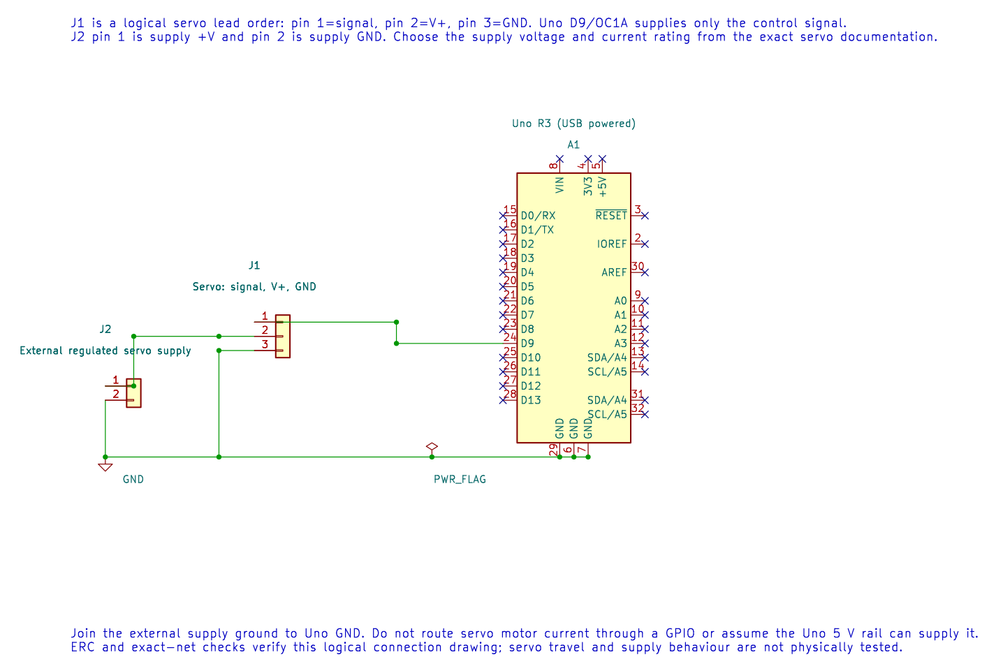
The editable KiCad schematic keeps the servo supply separate from the Uno logic supply. Check the exact servo and supply ratings before wiring.
Convert Timer Ticks to Pulse Time
Section titled “Convert Timer Ticks to Pulse Time”With a 16 MHz clock and divide-by-8, each Timer1 tick is 0.5 µs. Therefore, 3,000 ticks produce 3,000 × 0.5 µs = 1,500 µs. A 20 ms frame contains 40,000 ticks, so TOP is 39,999 when counting from zero.
The servo lab configures Timer1 mode 14 with D9/OC1A. Build it with python "atmega328p-labs/tools/build.py" 12-servo --compiler xc8. Timer1 is fully owned by this PWM setup; the input-capture or motor Timer1 example cannot be enabled at the same time.
Troubleshooting and Exercise
Section titled “Troubleshooting and Exercise”If the servo jitters or resets the Uno, check the supply current, grounding and wire length. If the motion reaches a hard stop, disconnect power and reduce the pulse range. Servo angle is not a direct property of OCR ticks; the mechanical response varies by unit.
Why does high_ticks=3000 request a 1.5 ms pulse at this timer setting?
Answer: Each tick lasts 0.5 µs, so 3,000 ticks last 1,500 µs. OCR values are timer counts, not degrees.
Code Walkthrough
Section titled “Code Walkthrough”SG90 servo pulse generation
Section titled “SG90 servo pulse generation”The example’s main() configures its peripherals, runs the algorithm and reports or displays the result. These source operations are listed in execution order:
(void)avr_timer1_pwm(8U, 40000U, 3000U);- Configures Timer1 mode 14 with prescaler 8; ICR1 becomes 39999, giving a 20 ms frame, and OCR1A starts at 3000 ticks (1500 us high).for (;;)- Repeats the foreground task indefinitely; each pass checks inputs, advances the calculation or services the peripheral shown below.OCR1A = 2000U;- Loads 2000 timer ticks for a 1 ms high pulse; Timer1 ticks at 0.5 us with the divide-by-8 prescaler._delay_ms(1000);- Waits for the stated interval; the foreground does no other work during this blocking delay.OCR1A = 3000U;- Loads 3000 timer ticks for a 1.5 ms high pulse; this is the nominal servo centre position.OCR1A = 4000U;- Loads 4000 timer ticks for a 2 ms high pulse; the servo endpoint depends on the actual servo.
Algorithm: At divide-by-8 each tick is 0.5 us. 40000 ticks make a 20 ms frame. Servo angle and safe travel depend on the actual unit; do not force a mechanical stop. Expected behaviour: Servo alternates approximately between 1, 1.5 and 2 ms pulse positions HAL source files in this repository: ATmega328P HAL on GitHub
References
Section titled “References”- Servo source and wiring record
- TowerPro SG90 Digital product information; this is one manufacturer’s variant and does not establish the ratings of every servo sold as SG90.
- Timer1 and PWM motor safety
- Follow the exact servo manufacturer’s voltage and pulse-range data.