TWI And I²C Bus Concepts
Two Shared Lines
Section titled “Two Shared Lines”The ATmega328P calls its peripheral TWI; it implements the commonly used I²C bus protocol. On the Uno R3, SDA is A4 and SCL is A5. Both lines are open-drain/open-collector style signals and need pull-up resistors to the bus logic supply. Devices share the lines and use addresses to determine which one should respond.
Choose pull-up values and bus voltage for the total bus capacitance, speed and attached devices. A 3.3 V module may not tolerate a 5 V pull-up. Use a suitable level translator or keep all bus devices at a compatible voltage.
Start, Address, Acknowledge
Section titled “Start, Address, Acknowledge”The controller begins a transaction with START, sends a 7-bit address plus a direction bit, and checks for ACK. Data bytes follow, each with ACK or NACK. STOP ends the transaction. Some register reads use a repeated START between the register-address write and the data read, without releasing the bus.
The bus speed is part of the electrical design. Standard-mode I²C uses up to 100 kHz, and fast-mode uses up to 400 kHz when all devices and the bus capacitance support it. A device’s data sheet may specify a lower maximum.
Addresses Are Passed as Seven Bits
Section titled “Addresses Are Passed as Seven Bits”The course TWI HAL accepts an unshifted seven-bit address such as 0x68; it adds the read/write direction bit during the transaction. Do not shift the address yourself before calling it. Address lists may also show an eight-bit write/read byte, so check how each document represents an address.
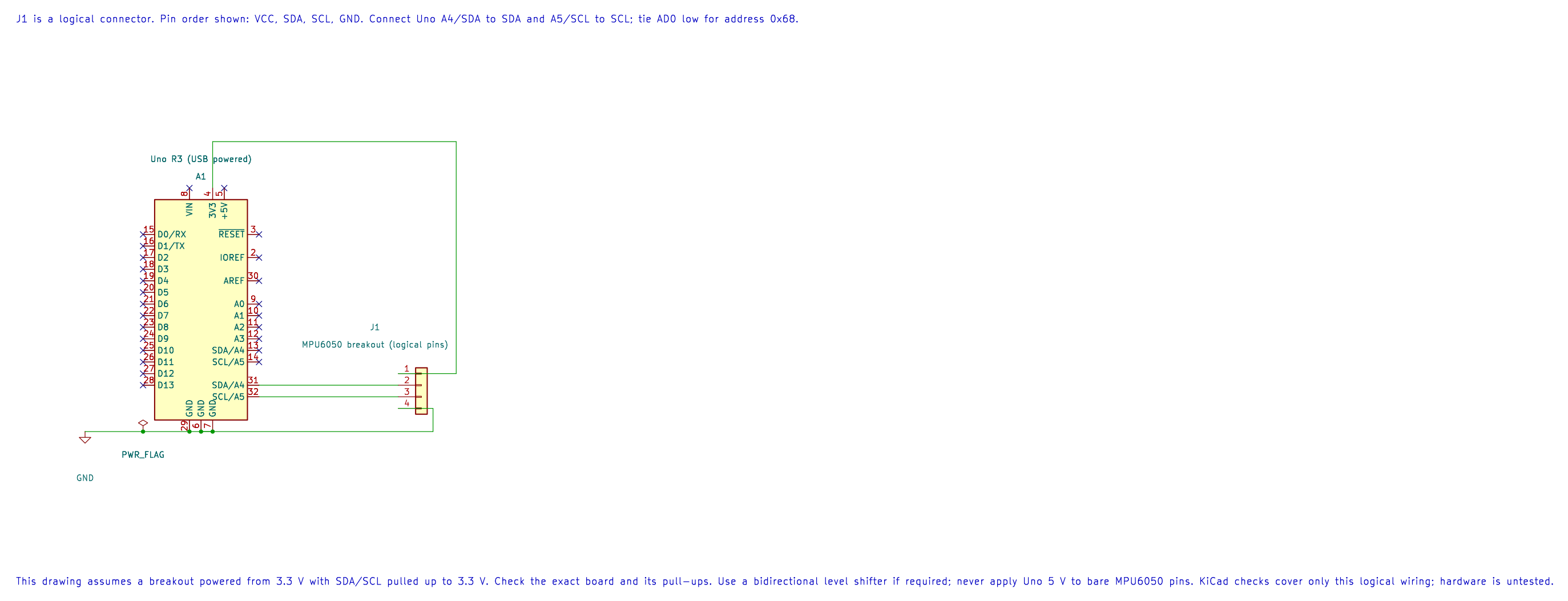
| Uno R3 | Compatible Breakout | Purpose |
|---|---|---|
| 3.3 V | VCC | Supply, only when supported by the breakout |
| A4 / SDA | SDA | Two-way data line |
| A5 / SCL | SCL | Clock line |
| GND | GND | Shared reference |
This drawing assumes a 3.3 V breakout with 3.3 V I²C pull-ups. Breakout boards differ: check the exact board’s power input, pull-up voltage and pin labels before wiring it to a 5 V Uno.
Build the address-probe example before using it on a bus:
python atmega328p-labs/tools/build.py 22-twi-scan --compiler xc8Exercise with Answer
Section titled “Exercise with Answer”Why does the bus need pull-up resistors if the controller can drive a line low?
Answer: The bus devices release the line to represent high and pull it low to represent low. The pull-up creates the high level; compatible devices can share the line without driving opposite push-pull levels against one another.
Code Walkthrough
Section titled “Code Walkthrough”Example code on GitHub:
Direct-Register TWI Identity Read
Section titled “Direct-Register TWI Identity Read”The example’s main() configures its peripherals, runs the algorithm and reports or displays the result. These source operations are listed in execution order:
uint8_t identity = 0U;- Clears the state/counter after its threshold is reached so the next interval starts from zero.DDRB |= _BV(DDB5);- Sets the Port B direction bits; a set bit selects output mode.PORTB &= (uint8_t)~_BV(PORTB5);- Sets or clears the Port B output latch. When the pin is an output, this determines its output level; on an input, it controls the pull-up.twi_result_t result = mpu6050_register_read(MPU6050_WHO_AM_I_REGISTER, &identity);- Stores this intermediate or output value for the next algorithm step. Check the units and range represented by each operand.if ((result == TWI_RESULT_OK) && (identity == MPU6050_WHO_AM_I_VALUE))- Tests the stated condition; the following block handles the matching case and the other path is skipped.PORTB |= _BV(PORTB5);- Sets or clears the Port B output latch. When the pin is an output, this determines its output level; on an input, it controls the pull-up.for (;;)- Repeats the foreground task indefinitely; each pass checks inputs, advances the calculation or services the peripheral shown below.
Algorithm: Directly controls TWBR/TWSR/TWCR/TWDR, checks each TWI status, uses repeated START, NACKs the final byte and bounds waits. Expected behaviour: D13 turns on when WHO_AM_I register 0x75 returns 0x68 HAL source files in this repository: ATmega328P HAL on GitHub
TWI address probe
Section titled “TWI address probe”The example’s main() configures its peripherals, runs the algorithm and reports or displays the result. These source operations are listed in execution order:
(void)avr_twi_init(100000UL);- Configures TWI for the requested bus rate and enables the peripheral. The bus still requires suitable external pull-ups and compatible signal voltage.(void)avr_uart_init(9600UL);- Configures USART0 for asynchronous 8N1. It chooses a baud divisor and normal/double-speed mode, programs UBRR0/UCSR0A/UCSR0C, then enables receive and transmit in UCSR0B.for (;;)- Repeats the foreground task indefinitely; each pass checks inputs, advances the calculation or services the peripheral shown below.for (uint8_t address = 8U; address < 0x78U; ++address)- Repeats whileaddress < 0x78Uis true;uint8_t address = 8Usets the starting state and++addressadvances it each pass.if (avr_twi_transfer(address, NULL, 0U, NULL, 0U, AVR_POLL_BUDGET) == AVR_OK)- The operation runs only after this API reports AVR_OK. Performs a bounded TWI transaction at the requested 7-bit address; the result reports address/data phase errors.(void)avr_uart_u16(address);- Formats an unsigned integer as decimal digits and sends them on USART0; it does not add a newline.(void)avr_uart_put('\n', AVR_POLL_BUDGET);- Waits for the USART transmit buffer within its poll budget, then writes the byte to UDR0._delay_ms(1000);- Waits for the stated interval; the foreground does no other work during this blocking delay.
Algorithm: Address 0x68 is printed as decimal 104. Do not shift an address before passing it to this HAL. Probe only devices whose datasheets allow an empty write transaction. Expected behaviour: Responding 7-bit addresses print in decimal; an empty bus prints none HAL source files in this repository: ATmega328P HAL on GitHub
References
Section titled “References”- Microchip, ATmega328P product documentation, TWI peripheral.
- TWI address probe lab
- Check the attached device’s data sheet for address, voltage, pull-up and bus-speed limits.
- MPU6050 wiring source and checks