ATmega328P USART Registers

Configuration and Data Registers
Section titled “Configuration and Data Registers”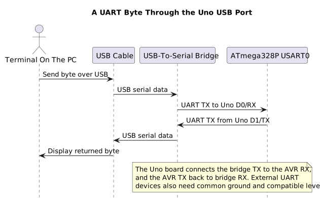
| Register | Purpose |
|---|---|
UBRR0H:UBRR0L |
Baud-rate divisor |
UCSR0A |
Status flags, double-speed selection and multiprocessor mode |
UCSR0B |
Transmitter, receiver and interrupt enables |
UCSR0C |
Asynchronous/synchronous mode, parity, stop bits and data width |
UDR0 |
Transmit data or the next received byte |
For asynchronous normal speed, the baud rate is approximately:
baud = F_CPU / (16 x (UBRR0 + 1))
At 16 MHz and 9600 baud, the ideal divisor is about 103.17. An integer divisor of 103 produces 16,000,000 / (16 x 104) = 9615.38 baud, about +0.16 percent. In double-speed mode, U2X0 changes the divisor from 16 to 8. Always calculate against the real clock and check the error against the receiving device’s tolerance.
Configure Asynchronous 8N1
Section titled “Configure Asynchronous 8N1”For 8 data bits, no parity and one stop bit, clear the UMSEL01:0, UPM01:0 and USBS0 selections and set UCSZ01:0. In UCSR0B, set RXEN0 and TXEN0. The register-level Lab 71 shows this setup directly, without the HAL. It uses finite polling loops and does not enable interrupts.
Do not let the direct-register program and the UART HAL configure USART0 at the same time. D0/RX and D1/TX also connect to the Uno’s USB-to-serial bridge. External devices on these pins can interfere with uploads or terminal traffic.
Build Lab 71 with either compiler to check the direct-register configuration:
python atmega328p-labs/tools/build.py 71-usart-register-echo --compiler gccpython atmega328p-labs/tools/build.py 71-usart-register-echo --compiler xc8Read Status Before the Data Byte
Section titled “Read Status Before the Data Byte”RXC0 indicates that a received byte is ready. UDRE0 means the transmit data register can accept another byte. It does not mean the previous frame has finished leaving the TX pin; TXC0 indicates complete transmission.
FE0, DOR0 and UPE0 report framing, overrun and parity errors for the buffered receive byte. Read UCSR0A before reading UDR0, then inspect those flags before accepting the byte. Reading UDR0 advances the receive buffer. If an error is present, define a recovery policy rather than silently treating the data as valid.
TXC0 is write-one-to-clear. A direct write of one clears it; a read-modify-write can accidentally clear a flag that became set between the read and write. Follow the data sheet’s prescribed write sequence. Other flags have their own rules, so do not treat every control/status register as ordinary memory.
Decide Between Polling and Interrupts
Section titled “Decide Between Polling and Interrupts”Polling is straightforward when the application can spend time waiting and bytes arrive slowly enough. Use an interrupt receiver and a bounded ring buffer when bytes may arrive during other foreground work. The interrupt service routine should copy the byte and its error state into the queue, then return; parsing and long responses belong in foreground code. A finite buffer can still overflow, so the application needs an overflow counter or other explicit recovery.
Exercises with Answers
Section titled “Exercises with Answers”- At 16 MHz, what baud rate does UBRR0=103 give in normal mode? About 9615 baud, approximately +0.16 percent from 9600.
- Does
UDRE0=1mean the final stop bit has left the TX pin? No. It only means UDR0 can accept a new byte. CheckTXC0when complete transmission matters. - Why read status before
UDR0? The framing, overrun and parity flags belong to the buffered receive byte. Reading data advances the receive buffer.
Code Walkthrough
Section titled “Code Walkthrough”Example code on GitHub:
USART Register-Level Echo
Section titled “USART Register-Level Echo”The example’s main() configures its peripherals, runs the algorithm and reports or displays the result. These source operations are listed in execution order:
for (;;)- Repeats the foreground task indefinitely; each pass checks inputs, advances the calculation or services the peripheral shown below.if (usart_get(&received))- Tests the stated condition; the following block handles the matching case and the other path is skipped.
Algorithm: Configures UBRR0, UCSR0A/B/C and UDR0 directly; checks RXC0 and per-byte FE0/DOR0/UPE0 before echoing. Expected behaviour: Each error-free received byte is echoed once; malformed or timed-out receives are ignored HAL source files in this repository: ATmega328P HAL on GitHub
Bounded UART echo
Section titled “Bounded UART echo”The example’s main() configures its peripherals, runs the algorithm and reports or displays the result. These source operations are listed in execution order:
(void)avr_uart_init(9600UL);- Configures USART0 for asynchronous 8N1. It chooses a baud divisor and normal/double-speed mode, programs UBRR0/UCSR0A/UCSR0C, then enables receive and transmit in UCSR0B.for (;;)- Repeats the foreground task indefinitely; each pass checks inputs, advances the calculation or services the peripheral shown below.avr_status_t status = avr_uart_get(&byte, AVR_POLL_BUDGET);- Use the linked public header for this function’s parameters, register ownership, blocking behavior and status values.if (status == AVR_OK)- Only enters the following block when the operation reports success.(void)avr_uart_put(byte, AVR_POLL_BUDGET);- Waits for the USART transmit buffer within its poll budget, then writes the byte to UDR0.
Algorithm: One 8N1 frame contains ten bits. At 9600 baud, a frame takes approximately 1.042 ms; the application must service reception before hardware buffering overflows. Expected behaviour: Each received byte is echoed once HAL source files in this repository: ATmega328P HAL on GitHub
References
Section titled “References”- Microchip, ATmega328P device documentation, USART register and baud-generation descriptions.
- Register-level USART example and HAL header.
- UART concepts and UART programming.